![]() A newsletter about soil, sediment, and groundwater characterization and remediation technologies
A newsletter about soil, sediment, and groundwater characterization and remediation technologies
This issue of Technology News and Trends highlights pilot-scale and demonstration projects to characterize and remediate sites with fractured bedrock contaminated by volatile organic compounds. Technologies applied in these projects involve subsurface injection of reactive amendments, in situ thermal conductive heating systems, and a range of geophysical tools to interpret a site’s existing or emplaced network of hydraulic fractures.
EPA Studies Efficacy of Potassium Permanganate ISCO in Fractured Bedrock
CLU-IN Resources
The U.S. EPA's Office of Superfund Remediation and Technology Innovation is assembling information on characterization and remediation of sites with contaminated fractured rock. Site-specific information in more than 150 brief profiles includes the nature and extent of contamination problems, affecting geology, and technologies undertaken or planned. View the new profiles, or submit additional profiles, and access additional resources at: www.clu-in.org/fracrock/.
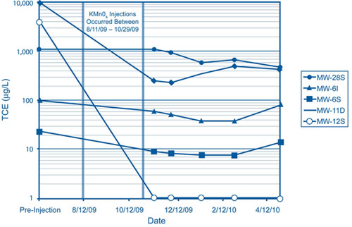
U.S. Environmental Protection Agency (EPA) Region 3 recently completed an in situ chemical oxidation (ISCO) pilot study for volatile organic compounds (VOCs) in fractured bedrock at the Valmont TCE Superfund Site near Hazleton, PA. Hydrofracturing technology was used to inject a high volume of potassium permanganate (KMnO4) slurry into isolated zones within the bedrock. The pilot study objectives were to evaluate effectiveness of ISCO as a stand-alone remedy, determine if KMnO4 slurry could be injected into the fractured bedrock, and estimate the radial influence of chemical oxidation around the injection wells and throughout the plume area. Results indicate that the injected KMnO4 slurry extended as far as 160 feet from the injection points and provided sufficient oxidant residence time to significantly decrease VOCs in the source area and throughout the plume.
The study site is located within an industrial park adjacent to a residential area. Past site operations included upholstery manufacturing and stain-guard treatment with trichloroethene (TCE). Releases of process waste contaminated the soil and groundwater, with groundwater contamination reaching approximately 110 feet below ground surface (bgs) and TCE concentrations as high as 26 mg/L in a bedrock aquifer. The contaminant plume is approximately 500 feet wide by 1,500 feet long.
The site is underlain by the Pennsylvanian-age Pottsville Group, which consists of interbedded conglomerate, sandstone, and siltstone fluvial deposits, with minor amounts of anthracite coal beds and shales. The average depth to competent bedrock is about 14 bgs, and the depth to groundwater ranges from 10 to 30 feet bgs. Groundwater migration is controlled primarily by the orientation of bedding plane fractures and joints within individual beds. Maximum fracture densities are associated with thinner, more brittle units near lithologic contacts. The predominant strike of bedding planes is east-northeast with a 7° dip to the northwest.
The matrix porosity measured in cores and obtained from geophysical logs averaged between 4-5%. Fracture porosity was calculated to be 0.041% based on fracture density data in geophysical logs and an estimated fracture aperture of 0.5 mm. These findings indicated that most of the groundwater flow occurs in fracture porosity, while most of the groundwater is stored in the matrix porosity. A groundwater divide running beneath the facility causes groundwater to flow along strike in both northeast and southwest directions.
Six injection wells were drilled to 150 feet bgs across the source area. Well spacing was based on a predicted 150-foot injection radius of influence. The injection wells were completed as open bedrock wells. Borehole geophysical logging was used to correlate stratigraphic units, locate fractures, and obtain porosity values to estimate the volume and vertical distribution of contaminant mass stored in the matrix porosity. Geophysical logging included gamma ray, temperature, fluid resistivity, heat pulse, normal resistivity, acoustic televiewer, caliper, compensated neutron/density porosity, and compensated sonic porosity tools.
One injection well was cored specifically to investigate the impact of matrix diffusion and to determine physical properties of the rock. Eighty core samples were collected in 1.5-foot increments, crushed onsite, placed in vials of methanol for VOC preservation, and shipped to an offsite laboratory for VOC analysis. A subset of core samples was analyzed for porosity, bulk density, organic carbon, permanganate oxidant demand, and metals. VOC analysis indicated an estimated maximum TCE concentration of 23 mg/L in matrix pore water. Results also indicated that approximately 95% of TCE mass in the sampled borehole originated in the upper 26 feet of rock and 86% of the contaminant mass is present in the sandstone matrix porosity. Permanganate oxidant demand ranged from 0.3 to 3.1 grams of oxidant per kilogram of rock. The highest rock oxidant demand was measured in organic rich siltstone/coals.
Selection of intervals for KMnO4 injection was based on matrix diffusion analysis, fracture location, and stratigraphic correlation with monitoring wells. Due to budgetary constraints, the number of injection intervals was limited to 3-4 zones per well. Each interval was isolated with a 10-foot dual-packer assembly and received 3,000 gallons of fluid and up to 2,000 pounds of KMnO4 in a slurry form.
A trailer-mounted dual-screw auger, continuous mixing system was used to mix KMnO4 solids with onsite water. The dry KMnO4 was loaded into a hopper on the mixing unit, where the solids were metered and blended with water to create slurry with a density of one pound of KMnO4 per gallon of water. Slurry was then pumped to a triplex hydrofracturing pump capable of operating at a flow rate of 80 gpm and pressure of 3,000 psi. Field tests indicated that the pump could handle a maximum slurry density of 3-4 pounds KMnO4 per gallon.
Straight water was used to initiate hydraulic fracturing and flush the pump and lines of solids once the target dosage was met. The highest breaking pressure observed during hydrofacturing was 800 psi, with 50-400 psi being typical. After fracture breakout, injection pressures dropped to 100 psi and then to below 50 psi. A total of 26,000 pounds of KMnO4 was injected at a typical rate of 60 gpm.
A network of monitoring wells surrounding the injection wells was equipped with pressure transducers to help estimate the radius of influence during injections. Based on pressure transducer data, the minimum radius of influence was typically 50-70 feet, with a maximum distance of 260 feet. Other indicators of radial distribution included color changes in monitoring wells and "daylighting" of oxidant on ground surfaces within the treatment area.
Selected monitoring wells were tested in the six months following the final injection event to track levels of VOCs, dissolved metals, KMnO4, and redox potential. Wells with visual indication of KMnO4 were not sampled for VOCs under the assumption that samples with KMnO4 would not contain detectable VOC concentrations. The oxidant was not neutralized prior to analysis. Results indicated VOC concentrations in shallow groundwater had significantly decreased near the injection wells, with source area wells exhibiting a 52-99% decrease in TCE concentrations and downgradient monitoring wells showing an average 67% decrease (from >300 to <100 ug/L) (Figure 1). At the leading edge of the plume, approximately 735 feet downgradient of the nearest injection well, a 25% decrease in VOC concentrations was observed.
Rebound in some wells was seen three months after the final injection, but KMnO4 was visually observed in some injection and monitoring wells for more than a year. Decreasing contaminant concentrations throughout the plume were accompanied by increases in oxidation potential, which suggested decreases in contaminant concentrations were due to contaminant destruction rather than dilution.
An estimated 10,500 pounds of TCE mass were destroyed during the pilot study--the mass of TCE stoichiometicly destroyed by 26,000 pounds of KMnO4 minus an estimated 2% loss due to native oxidant demand and other processes. The cost of injection (including hydrofracturing, water tank rental, and KMnO4 material) was approximately $250,000, or about $25 per pound of TCE destroyed. Other project costs included $87,000 for injection wells, $25,000 for coring, $40,300 for a matrix diffusion study, and $26,000 for borehole geophysics.
Based on the pilot study results, EPA Region 3 has selected ISCO as the final groundwater remedy. Full-scale ISCO is anticipated to involve three additional injection wells to treat the complete source area and restore the entire plume area to beneficial use.
Contributed by Bhupi Khona (khona.bhupi@epa.gov or 215-814-3213), Brad White (white.brad@epa.gov or 215-814-3217), and Bruce Rundell (rundell.bruce@epa.gov or 215-814-3317), U.S. EPA Region 3
U.S. Navy Demonstrates Thermal Conductive Heating for DNAPL Removal in Fractured Rock
Thermal conductive heating (TCH) was demonstrated on a pilot scale in 2008-2009 to remove TCE, cis-dichloroethene (DCE), and vinyl chloride mass from fractured rock at the Naval Air Warfare Center (NAWC) site in West Trenton, NJ. Project objectives were to reduce contaminant lifespan in the fractured rock and reduce aqueous-phase contaminant flux and concentrations in the target 400-ft2 by 740-yd3 treatment area. An estimated 530 pounds of chlorinated VOCs (CVOCs) were removed (an estimated 69-84% mass reduction) through active heating of the subsurface over 14 weeks. Results of the demonstration, which was funded by the Environmental Security Technology Certification Program (ESTCP), will be used to develop guidance on using TCH to remove contaminant mass.
Since 2002, the NAWC has served as a demonstration site for investigative and remedial technologies explored by the U.S. Geological Survey, U.S. Navy, universities, and industry. Mudstone bedrock in the area is generally encountered 5 feet bgs. Most of the soil in the area of the primary contaminant plume was removed by the Navy during NAWC construction in the 1950s, leaving relatively competent bedrock close to site surface. Site investigations indicate that an area covering more than 5 acres and extending to a depth of over 200 feet bgs was contaminated by TCE used for jet engine testing in the 1950s through 1990s. A pump-and-treat system has operated since the mid 1990s to treat groundwater with pre-treatment CVOC concentrations exceeding 600,000 ug/L. Aqueous and dense nonaqueous phase liquid (DNAPL) forms of TCE as well as aqueous-phase degradation products such as cis-DCE and vinyl chloride exist in water of the bedrock fracture network, where contaminants are sorbed to the rock matrix at various distances from the fracture surface.
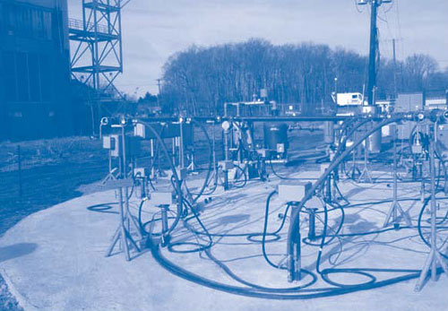
The field demonstration involved installing 15 heater borings, each equipped with a vapor extraction screen, to a depth of 55 feet bgs. Electricity from an adjacent power supply was applied to the 15 heater borings at depths of 5 to 55 feet bgs and a rate of 210 kW (Figure 2) to reach a target temperature of 100°C.
The heating system operated continuously for 98 days, injecting a total of 493,000 kWh of electricity into the treatment zone. All subsurface zones above 35 feet bgs reached temperatures of 99-110°C, consistent with in situ boiling temperatures of groundwater. At 40-50 feet bgs, temperatures increased to 70-80°C but remained below the boiling point of water.
Air, steam, and fluids were extracted from the bedrock at 15 recovery points through stainless steel well screens connected to flexible hoses. Contaminated water, condensed water, and CVOC vapors passed through an off-gas vapor and liquid treatment system consisting of one 55-ft2 heat exchanger, a 150-scfm positive displacement blower, two 1,000-pound granular activated carbon units, and an 18-ton chiller. Water exiting the system was diverted to an existing onsite groundwater treatment plant.
Based on photoionization detector readings and observed flow rates, approximately 500 pounds of total VOCs were removed from 740 yd3 of bedrock by way of vapor extraction. Based on laboratory data and actual flow rates, an estimated 30 pounds of VOCs were additionally removed from the water and condensed stream.
TCE, cis-DCE, and vinyl chloride concentrations were measured in three rock cores at 5-foot intervals from 5 to 55 feet bgs prior to heating and in three new rock cores one week after heating ended. Results indicated total VOC concentrations were as high as 277 mg/kg prior to heating. After heating, some samples of the matrix were below 5 mg/kg but remained high (100-275 mg/kg) in intervals associated with distinct fracture zones. Higher than expected flow of cold groundwater in these fracture zones during heating likely led to incomplete heating of surrounding rock. VOC concentrations in larger matrix blocks with no evident fractures were reduced to levels below 5 mg/kg.
The expected groundwater extraction rate due to in situ boiling of water and steam removal was 0.1-0.2 gpm; the actual rate measured during the pilot test was 2-3 gpm. This 10-fold increase was attributed to the co-location of vapor recovery wells in the same boreholes as heater wells and the extension of well screens below the water table to the bottom of the borehole (55 ft bgs). This design configuration created a situation where steam generated along the heater beneath the water table periodically pushed water up and out of the vapor recovery well.
An estimated 8,600-17,200 gallons of water were expected to be extracted during heating; however, 270,000 gallons were actually extracted. Temperature monitoring and water and energy balances indicated that the unexpectedly high rates of groundwater extraction from the treatment zone caused water to flow through the fractures and limit the rates of subsurface heating and VOC removal. Higher rates of VOC removal are expected in full-scale TCH applications that limit groundwater extraction and inflow.
The higher groundwater flux also caused the treatment zone to experience a 65% heat loss as compared to the 50% rate assumed in project design. For the TCH process to be effective in this setting, the flow of cold and contaminated groundwater into the treatment volume must be lower and/or controlled. Although this mechanism is expected to have less impact in full-scale applications where the ratio of surface area to volume of fractures decreases with scale, the influx of groundwater may be limited by using larger-diameter vapor extraction wells to allow the steam to bubble through standing water (without pushing it out), reduce steam velocity, and reduce the amount of entrained water extracted from the wells; installing a hydraulic barrier such as a freeze-wall, grout curtain, or sheet piles where possible; or injecting steam into water-bearing fractures to displace groundwater and heat the fracture system.
EPA Studies Hydraulic Fracturing
Due to public concerns regarding the hydraulic fracturing process used in natural gas production, EPA's Office of Research and Development is studying potential relationships between hydraulic fracturing and drinking water. The process commonly uses different techniques to emplace larger fracture networks when compared to processes used to remediate contaminated sites. Learn more about the issues and study findings as they become available at: http://water.epa.gov/type/groundwater/
uic/class2/hydraulicfracturing/.
Researchers at Queen's University in Kingston, Ontario, Canada are nearing completion of a concurrent laboratory treatability study and numerical modeling to evaluate VOC removal rates, the necessary temperatures, and expected duration for effective TCH applications in fractured rock. The treatability study includes measuring dry bulk density, fraction of organic carbon, matrix porosity and pore throat distribution; determining intrinsic permeability of siltstone, limestone, sandstone, and dolostone samples collected from NAWC and other sites; and conducting bench-scale heating tests. Numerical modeling focuses on the influence of inflowing cold groundwater, heating dynamics in the rock matrix, and back-diffusion effects following TCH application. Final results and additional details of the field demonstration and treatability study will be available in an ESTCP cost and performance report to be released in 2011.
Contributed by Carmen Lebron, NAVFAC Engineering Service Center (carmen.lebron@navy.mil or 805-982-1616) and Devon Phelan, TerraTherm, Inc. (dphelan@terratherm.com or 978-343-0300)
USACE Integrates Fracturing and Iron/Carbon Injections at Colorado Site
The U.S. Army Corps of Engineers (USACE) performed a large-scale pilot test in 2009 for remediating TCE-contaminated groundwater at the "Atlas 12" formerly used defense site. Hydraulic fracturing was conducted to optimize emplacement of a zero-valent micro-iron/complex carbon amendment that chemically and biologically reduces contaminants in bedrock. Three-dimensional (3-D) mapping was used to monitor the amendment's subsurface pathways and evaluate its in situ performance. Nine months after fracturing and injections, changes in volume and concentration-weighted averages estimated an 82% TCE mass reduction in the contaminant source area.
The Atlas "E" Missile Site No. 12 (Atlas 12) is a former F.E. Warren Air Force Base facility in Windsor, CO. Site investigations in 1996 identified TCE and petroleum contamination in soil and shallow groundwater surrounding the facility’s launch and service building, where TCE was used from 1960 to 1965 to flush the missile fuel tanks. The waste TCE and residual rocket fuel was released to a wastewater drainage sump that subsequently seeped into groundwater.
The water table at the facility is approximately 35-45 feet bgs. Prior to the treatment, the groundwater had TCE concentrations reaching 3,600 µg/L and associated degradation products. The site is underlain by a thin surficial soil layer of eolian sand and silt up to 10 feet thick that overlie 45-50 feet of sandstone, followed by a transitional zone of shale approximately 130 feet thick. The saturated zone targeted for pilot-scale treatment is estimated to be 30-40 feet thick.
The pilot test focused on groundwater treatment in the source area and portions of the distal end of the plume. Over 30 days in the spring of 2009, fracturing was conducted from nine pre-drilled boreholes using a skid-mounted fracture rig, primary and backup sets of downhole fracturing tools, and biodegradable fracture chemicals such as a linear protein gel viscosifier. Hollow stem augers were used to temporarily case the upper 30 feet of each hole and maintain borehole stability until fracturing was complete. Additional stability was gained by installing temporary 4-inch-diameter PVC casing that extended to the bottom of each borehole. Based on earlier core tests indicating rock cohesion values of 50-60 kPa, a triplex pump was used for fracturing and amendment delivery to the target bedrock in 5-foot increments at depths of 35-63 feet bgs.
Applied pressures for initiating fractures in the source area ranged from 124 to 838 psi, with the higher break pressures generally relating to deeper fractures or overburden pressure rather than cohesive strength of the bedrock. The average fracture propagation pressures ranged from 140 to 700 psi. Fracture pressures were typically lower in the distal plume area.
During fracturing, 6,000-32,000 pounds of amendment in the form of a biodegradable, linear protein gel slurry were emplaced in each borehole. The slurry contained sand and potable water mixed at a design loading rate of 0.27% amendment (by weight) for the seven source area boreholes and 0.10% amendment for the two boreholes reaching the distal end of the plume. Discrete fracture intervals were created by placement and pressurized inflation of straddle packers below and above the desired fracture depth at approximate 4-foot intervals. Slurry pumping rates ranged from 12 to 65 gpm with an average of 31 gpm.
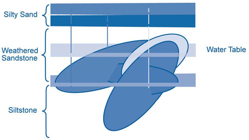
Tilt sensors at ground surface were deployed to characterize each fracture's length, width, thickness, asymmetry, orientation, and angle of ascent (Figure 3). Tiltmetric data were correlated with operational fracturing data such as pressures and flow rates over time to create a dynamic 3-D model depicting individual boreholes as well as the entire fracture network.
A total of 188,085 pounds of amendment was emplaced in bedrock at target depths of 35-63 feet bgs, with an average borehole delivery rate of 2.2 pounds of amendment per gallon of injected slurry. The overall delivery efficiency was estimated at 98% with some slurry loss due to hydraulic communication with an open, pre-drilled borehole. This loss was rectified by installing a utility packer inside the well casing.
FRTR Addresses Fractured Rock
The Federal Remediation Technologies Roundtable (FRTR) meeting on November 9, 2010, focused on characterization and remediation of sites with fractured bedrock. To view the presentations and meeting summary, visit the FRTR online at: http://www.frtr.gov/meetings1.htm.
Field observations and tilt response showed that the radius of fracture emplacement in the bedrock reached nearly 80 feet, with a typical fracture overlap of 30-50%. Tiltmetric data indicated fractures with a median thickness of 0.33 inches and an average length of 79 feet along their inclination and 65 feet horizontally. Six percent of the fractures were nearly horizontal, 12% slightly ascended, 57% moderately ascended, and 25% strongly ascended toward ground surface. Source area mapping indicated that the slurry had reached a 64,000 ft2 area encompassing 52 individual fractures.
TCE concentrations were reduced more than 90% over the 9-month monitoring period following injection/fracturing in areas receiving the largest quantities of amendment and where fractures extensively interconnected and overlapped. The monitoring well with the highest pre-treatment TCE concentration (3,600 µg/L) had 160 µg/L TCE at the end of monitoring. Two nearby wells showed pre- and post-pilot test TCE concentration declines from 2,300 to 120 µg/L and 1,700 to 150 µg/L. TCE reductions greater than 50% were observed in areas with lower amendment mass, fewer fractures, and greater distance between boreholes.
Simultaneous declines of TCE and cis-DCE and production of ethene indicated that chemical reduction facilitated by zero valent micro-iron was the primary mechanism for contaminant degradation. The monitoring well with the highest cis-DCE concentration (470 ug/L) prior to treatment had 97 µg/L cis-DCE at the end of monitoring, and surrounding wells showed reductions from 110 to 13 µg/L and 100 to 10 µg/L. Biological reduction facilitated by the complex carbon was identified as a secondary degradation mechanism, as evidenced by redox conditions changing from aerobic to anaerobic and limited cis-DCE production in wells not exhibiting chemical reduction.
The unit cost for hydraulic fracturing, geophysical mapping, and over 100 tons of amendment is estimated at $8/ton of bedrock treated. Costs for the amendment and hydraulic fracturing totaled approximately $700,000.
Errata
Regarding the October 2010 article "In Situ Thermal Desorption Minimizes Cleanup Duration at Dunn Field BRAC Site," the estimated total VOC mass was 12,000 pounds. It was incorrectly cited as 1,200 pounds in the article.
The USACE is now integrating the pilot test results into design of a full-scale remedial action to be initiated at Atlas 12 in 2011. Full-scale application is expected to take over three years and include an amendment fracture network, institutional controls such as restricted groundwater use, and a long-term groundwater monitoring plan.
Contributed by Jeff Skog, USACE (jeffery.a.skog@usace.army.mil or 402-995-2739), Gordon Bures, Frac Rite Environmental Ltd., (gbures@fracrite.ca or 403-265-5533), and Dana Swift, North Wind, Inc. (dswift@northwind-inc.com or 208-528-8718)