- Featured Articles
- Combined Technologies: Thermal Conduction Heating and Steam Enhanced Extraction Removes 99% of Estimated Contaminant Mass
- Combined Technologies: ERH and MPE Implementation Accommodates Major Ground Surface and Subsurface Obstructions
- Combined Technologies: Electro-Thermal Process with Steam Expected to Reduce Pump and Treat Duration
- Resources
 Download This Issue in Adobe PDF® Format
(2.09MB/11pp/PDF)
This issue of Technology News & Trends highlights in situ thermal (IST) technologies such as electrical resistance heating, steam enhanced extraction, and thermal conduction heating. These technologies have been used more often in recent years, primarily to remove non-aqueous phase liquid in contaminant source areas. Since fiscal year (FY) 2005, IST technology has been selected for use at 18 Superfund sites in addition to numerous RCRA corrective actions, brownfield sites, or military installations needing accelerated cleanup of highly defined source areas.
| Superfund Sites with Proposed, Designed, or Implemented IST Technology (FY 2005 through FY 2011) |
|---|
| Alaric Area Groundwater Plume, Tampa, Florida Bridgeport Rental & Oil Services, Bridgeport, New Jersey Chemical Leaman Tank Lines, Inc., Logan Township, New Jersey Cleburn Street Well, Grand Island, Nebraska Commencement Bay-South Tacoma Channel, Tacoma, Washington Former Spellman Engineering, Orlando, Florida Frontier Fertilizer, Davis, California Grants Chlorinated Solvents Plume Site, Grants, New Mexico Groveland Wells, Groveland, Massachusetts Memphis Defense Depot, Memphis, Tennessee NASA Marshall Space Flight Center, Huntsville, Alabama Omega Chemical Corporation, Whittier, California Paducah Gaseous Diffusion Plant (U.S. Department of Energy), Paducah, Kentucky Pemaco, Maywood, California Savannah River Site (U.S. Department of Energy), Aiken, South Carolina Silresim Chemical Corp., Lowell, Massachusetts Solvents Recovery Service of New England, Southington, Connecticut South Municipal Water Supply Well, Peterborough, New Hampshire |
The increased IST applications have brought new lessons learned about effectively combining these technologies, handling issues such as water influx or tidal influence, treating the extracted vapors, optimizing the use of energy needed to operate IST equipment, and operating the systems amid ongoing site activities.
FEATURED ARTICLES

Combined Technologies: Thermal Conduction Heating and Steam Enhanced Extraction Removes 99% of Estimated Contaminant Mass
Contributed by Denny Timmons and Greg Sandlin, Arnold Engineering and Development Complex; Susan Trussell, U.S. Army Corps of Engineers/Tulsa District
Recent treatment of a contaminant source zone at Arnold Air Force Base, Tennessee, involved thermal conduction heating (TCH) in a shallow aquifer and steam enhanced extraction (SEE) in an intermediate aquifer. As part of a RCRA corrective action for the base's solid waste management unit (SWMU) 10, this combined technology approach to in situ thermal (IST) technology was designed to remove large amounts of dense non-aqueous phase liquid (DNAPL) in multiple water-bearing zones at depths reaching 90 feet below ground surface (bgs) and with strong contrasts in lithology. The approach also was required to accommodate critical base activities at an adjacent model shop used for ongoing machining and fabrication of military equipment.
From 1950 to 1972, an estimated 31,000 gallons of chlorinated solvents were reportedly disposed by infiltration in an unlined leach pit at SWMU 10. The highest identified concentrations of primary contaminants of concern in groundwater were 135,000 micrograms per liter (µg/L) tetrachloroethene (PCE) and 8,910 µg/L 1,1,1-trichloroethane (TCA). In the absence of competent confining layers in the subsurface, contaminants migrated vertically through three aquifers. Permeability in the treatment zone subsurface differs by at least three orders of magnitude between the shallow and intermediate aquifers.
DNAPL was observed over a half-acre area through observations of free-phase DNAPL, hydrophobic dye tests, and elevated soil and groundwater concentrations approaching the aqueous solubility limit of 150,000 µg/L for PCE. Dissolved-phase contamination extended more than two miles downgradient of the source area and posed a potential risk to regional groundwater and surface water (Figure 1).
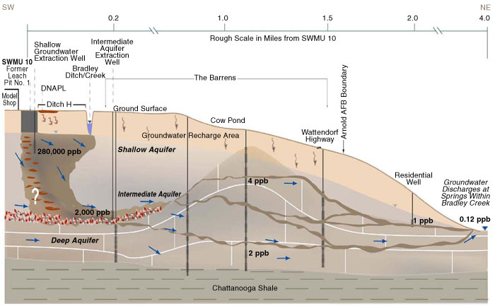
Figure 1. Regional water potentially affected by PCE DNAPL at SWMU 10 prior to remediation activities.
Initial corrective actions involved use in 1996 of ex situ low temperature thermal desorption for over 6,000 cubic yards of soil to depths of 16 feet bgs. To treat the intermediate aquifer on an interim basis and reduce contaminant migration, a groundwater pump and treat system operated from 1996 to 2009.
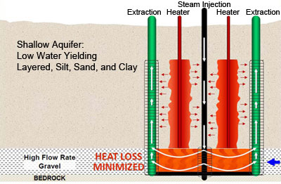
Figure 2. Configuration of each heating and extraction nest at SWMU 10.
The target IST treatment zone extends from 10 feet bgs to approximately 90 feet bgs, yielding an estimated treatment volume of 66,700 cubic yards. The 85-foot depth of extraction wells was anticipated to fully transect the deep aquifer and reach the top of underlying bedrock, which would minimize heat loss laterally through gravel above the bedrock (Figure 2). Preconstruction studies including pump tests indicated that layered silt, sand, and clay of the shallow aquifer could sufficiently convey heat from the steam injection and heater wells to the extraction wells. The heat velocity was estimated at 0.05 feet/day within the TCH treatment zone and 7.1 feet/day within the underlying SEE treatment zone.
The combined TCH-SEE treatment approach was designed and optimized through numerical simulation. The shallow aquifer was heated with 164 heaters installed to depths of 50 to 65 feet bgs. The intermediate aquifer was heated using 11 steam injection wells completed in the basal gravel/upper bedrock zone at 90 feet bgs. Forty-two vapor extraction wells and 23 multiphase extraction wells completed to depths between 45 and 90 feet bgs were located within and surrounding the treatment zone for hydraulic and pneumatic gradient control during treatment. Although steam temperatures were expected to vary, depending on the amount of pressure that could be delivered to the subsurface, target temperatures for thermal conductance were set at 250-365°F.
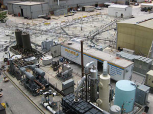
Figure 3. Completed IST system covering approximately 27,400 square feet of industrial space at Arnold Air Force Base.
A 1- to 2-inch layer of shotcrete was installed over the entire treatment area to serve as a soil cap that would minimize water infiltration and retain heat in the treatment systems (Figure 3). The extracted vapor was treated by thermal oxidation, and extracted groundwater was treated by air stripping and activated carbon. Resulting vapors were treated by a thermal oxidizer prior to exhaust through an acid gas scrubber.
To maximize DNAPL removal, TCH was coupled with SEE in the site's western zone containing the majority of DNAPL at greater depths, while only TCH was implemented in the eastern zone having DNAPL at shallower depths. Treatment in the eastern zone was deemed complete in December 2010 after seven months of TCH operation. PCE concentrations in soil and groundwater at that time had dropped to below the target remediation goals of 150 µg/L for groundwater and 5,000 µg/kg for soil. TCA concentrations were far below PCE concentrations.
Treatment in the western zone extended over another nine months, until September 2011 when asymptotic mass removal was encountered. IST performance differences in this zone were attributed to an uncontained influx of shallow water that served as a heat sink causing greater saturation and cooler temperatures below the soil cap, which together inhibited vapor recovery and increased heat loss from the treatment system. Thermal imaging confirmed existence of a large zone that was significantly cooler (86-124°F) than surrounding areas (reaching 209°F). Possible sources of the cooler water included precipitation, building roof drains, sumps, stormwater conveyance, or subsurface utilities.
In mid 2011, approximately 290 feet of boundary interceptor trenches equipped with extraction sumps or stormwater bypasses were installed in the western zone to collect the cool, shallow water. Other efforts to improve system performance involved modifications such as adding a water removal knockout vessel to the vapor train and boosting discharge capacity of the treated water. Well field enhancements to target DNAPL hotspots included adding four shallow steam injection wells, one multiphase extraction well, and 68 shallow vapor extraction wells; installing 12 additional heaters and replacing 25 heaters; lifting 15 heaters to the target shallow soil; and covering the treatment zone surface with insulation.
Although target remediation goals (performance metrics) could not be achieved within all portions of the western zone, the revised goals for groundwater and soil in these areas (1,500 µg/L and 100,000 µg/kg, respectively) were achieved. Use of the combined TCH-SEE application resulted in removing approximately 165,000 pounds of PCE (99% of the estimated mass) over 16 months. IST implementation at SWMU 10 cost approximately $10 million. Additional costs for related infrastructure improvements totaled approximately $350,000, including an estimated $250,000 to extend electricity service, $50,000 to modify the water system, and $50,000 to clear the area needed for IST operation.
Use of thermal remediation technology reduced the duration of groundwater hydraulic containment and post-thermal polishing requirements at SWMU 10 from hundreds of years to less than a decade, achieving the Air Force goal of accelerated project closure. Continued post-thermal monitoring and modeling is underway to evaluate if additional downgradient groundwater remediation is required.

Combined Technologies: ERH and MPE Implementation Accommodates Major Ground Surface and Subsurface Obstructions
Contributed by Sairam Appaji, U.S. EPA Region 6
In late 2011, an enhanced electrical resistance heating (ERH) system integrated with multiphase extraction (MPE) began operating at the Grants Chlorinated Solvents Plume Superfund site in Grants, New Mexico. The treatment area encompassed 30,400 square feet at an active dry cleaner facility adjacent to residential properties and bisected by a three-lane state highway and a six-inch natural gas distribution line. Preliminary project results show that 94% and 100% of the estimated total contaminant mass was removed from soil and groundwater, respectively, and suggest design or operation approaches to address onsite infrastructures.
The site's primary contaminant of concern is tetrachloroethene (PCE) resulting from past releases of chlorinated solvents at an abandoned dry cleaner as well as the existing facility. The site's soil consists primarily of clay and silty sand with an estimated porosity of 0.28. The depth to groundwater in the shallow zone is approximately 5-6 feet below ground surface (bgs). Hydraulic conductivity and velocity of groundwater in the shallow groundwater zone is estimated at 21-32 feet per day and 69 feet per year, respectively. Vapor intrusion into buildings above the plume was addressed in 2008 by installing mitigation systems such as synthetic barriers at 14 homes.
Prior to in ERH-MPE implementation, the highest PCE concentration detected was approximately 50 milligrams per liter (mg/L) in groundwater and 75 milligrams per kilogram (mg/kg) in soil. Trichloroethene (TCE) and cis-1,2- dichloroethene (DCE) concentrations in source area groundwater were 2 mg/L and 1 mg/L, respectively, and vinyl chloride was generally below detection limits. Based on soil data collected during system installation, the original volatile organic compound (VOC) mass estimate of 3,000 pounds was revised to about 1,200 pounds.
The 33,000-cubic-yard target treatment zone was divided into four subareas with different target treatment depths and positions relative to the natural gas line. The target depths ranged from 25 to 40 feet bgs, based on site investigations before and during remedial design. Prior to construction, removal of the onsite roadway infrastructure (from ground surface to 10 feet bgs) was required in accordance with U.S. Department of Transportation regulations. At the active dry cleaning facility, a false floor was installed to provide a vapor barrier, maintain normal interior temperatures, and allow installation of upgraded piping and wiring.
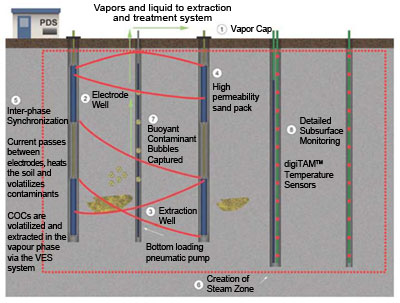
Figure 1. Conceptual design of enhanced ERH system used at the Grants Chlorinated Solvents Plume site.
The ERH system (Electro-Thermal Dynamic Stripping Process [ET-DSP™]) comprised 258 eight-inch-diameter and 6.5- to 10-foot-long electrodes installed in 109 vertical and 12 angled soil borings drilled on 20-foot centers. Depending on the target depth of each subarea, one to three electrodes were installed in each boring. Electrode spacing was based on the soil's electrical resistivity, which ranges from 9.3 to 10.8 ohm-meter. To assure full vertical heating, the bottom of the lowest electrode in each boring was installed near the base of the target treatment depth, and the top of the uppermost electrode in each boring was completed at 3.5 to 4 feet bgs (Figure 1).
MPE system construction involved installing 64 four-inch-diameter stainless and carbon steel vertical and angled wells to extract vapor and liquid mobilized by the heating process; the wells were installed to the bottom of the treatment zone. Each well was equipped with a pneumatic pump or slurper tube, depending on well depth, to support fluids recovery through screens extending from 4 feet bgs to the well's bottom. The system also included 27 two-inch-diameter fiberglass wells to extract vapors from the vadose zone only.
Field adjustments were required throughout construction of both systems to account for the utility infrastructure; a more robust pre-construction utility survey would have minimized adjustments. Since all vertical and horizontal components of the systems required burial, construction as well as treatment operations also would have benefited from more extensive traffic controls to protect onsite workers and allow more constant traffic flow.
To provide a continuous thermal and vapor cap over the constructed system, a layer of shotcrete was placed above treatment areas not already covered by concrete or asphalt. The power delivery system (PDS) included two new electrical service units installed on an existing high-voltage distribution network and two (1,500 kVA and 2,000 kVA) new three-phase transformers. Unit sizes were selected to meet electricity needs of the extraction/treatment equipment as well as a ventilation system in the dry cleaning building.
A 400 standard cubic foot per minute (scfm) blower conveyed extracted fluids from the treatment zone to the treatment system. The air flow rate averaged 1-2 scfm from each shallow vapor recovery well and 8-10 scfm from each deep well. Water was treated through an oil-water separator, air stripper, and two granular activated carbon (GAC) units operating in series while vapor was treated with GAC only.
Photoionization detector (PID) readings and laboratory analysis of effluent vapors were used throughout heating to determine the need for replacing GAC in the vapor treatment system. PID data also were used to determine when vapor or liquid extraction adjustments were warranted, such as increased extraction rates when higher contaminant concentrations were encountered. The water treatment system required upgrades during operation to address influent with a solids content higher than anticipated, which caused persistent scaling.
Active heating began in December 2011. The process was monitored through 295 temperature sensors at various depths and positions: seven 25-foot strings with 14 sensors, seventeen 40-foot strings with nine sensors; one 70-foot horizontal string with 24 sensors, and one 60-foot angled string with 20 sensors. Continuous remote monitoring of temperatures allowed operators (working 24/7) to respond in real time to subsurface conditions. Operator adjustment of the current between electrodes to address the soil's varying electrical and lithological properties was aided by inter-phase synchronization technology. Over the course of treatment, data on temperatures and other operating parameters were available to the project team on a dedicated project web page. Monitoring found that portions of the dry cleaning building's interior experienced temperatures warmer than desired, which could have been minimized by insulating the false floor.
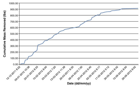
Figure 2. Cumulative VOC mass removal over time via vapor phase.
The target temperature of 92°C (the azeotropic boiling point of PCE) was reached about 90 days after startup. Operations continued at this temperature for 96 additional days until PCE concentrations in soil were below the cleanup objective (0.327 mg/kg) at 15 of 18 sampling locations. Similar trends were found for TCE, while cis-1,2-DCE concentrations were below the target concentration (180 µg/kg) at all sampling locations. At system shutdown, VOC mass removed through the vapor stream totaled more than 900 pounds (Figure 2).
Over 2,550,000 gallons of water were injected into the electrodes during active heating, at an average rate of 9.73 gallons per minute. The total amount of electricity used to heat the subsurface was 4,821 Megawatt-hours, which was lower than estimated during design-phase soil resistivity testing; the lower rate was partially attributed to site conditions such as variable conductivity. Costs for implementing the integrated ERH-MPE system at this Superfund site totaled approximately $7,000,000 ($210 per cubic yard), including $550,000 for electricity (at $0.11 per kilowatt-hour with fees).
Decommissioning of above-grade portions of the ERH-MPE system was completed over 10 days in July 2012, and abandonment of wells and removal of below-street components are underway. Complete site restoration is anticipated in December 2012. The EPA Region 6 office is now evaluating feasibility of using enhanced reductive dechlorination to treat the residual PCE hotspots and determining the need for additional vapor intrusion mitigation in any affected buildings.

Combined Technologies: Electro-Thermal Process with Steam Expected to Reduce Pump and Treat Duration
Contributed by Derrick Golden, U.S. EPA Region 1 and Janet Waldron, Massachusetts Department of Environmental Protection
From August 2010 to February 2011, the U.S. Environmental Protection Agency (EPA) conducted in situ thermal (IST) treatment using the Electro-Thermal Dynamic Stripping Process (ET-DSP™) at the Groveland Wells Superfund site in Groveland, Massachusetts, to address a trichloroethene (TCE) source area. The IST technology was expected to reduce treatment time of contaminated groundwater by the existing pump and treat (P&T) system, particularly below the source zone where elevated concentrations of TCE (up to 96,000 µg/L) had persisted after 11 years of P&T and 10 years of soil vapor extraction (SVE). After six months of operation, IST treatment removed over 1,300 pounds of volatile organic compounds (VOCs) and 18 gallons of non-aqueous phase liquid (NAPL), and contributed to a 97% reduction of TCE concentrations in groundwater.
A 1979 investigation by the Massachusetts Department of Environmental Protection (MassDEP), formerly the Department of Environmental Quality Engineering, revealed TCE concentrations above drinking water standards in two municipal water supply wells. The wells were shut down, and in 1982, the 850-acre contaminated area was placed on the National Priorities List. The main source of contamination was determined to be the Valley Manufacturing Products Company where cutting oils, lubricants, and hydrocarbon solvents were being used for machining and degreasing. Subsurface soil was contaminated with TCE and other VOCs, including methylene chloride, 1,1,1-trichloroethane, tetrachloroethene, and cis-1,2-dichloroethene (1,2-DCE). Analysis of soil gas samples collected from under the plant building indicated total VOC concentrations as high as 1,300 parts per million. A 350- to 1,000-foot-wide groundwater plume consisting primarily of TCE and 1,2-DCE was found to extend approximately 3,900 feet northward from the source area (see Figure 1).
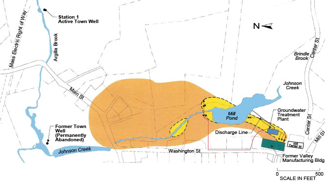
Figure 1. Location of municipal supply wells (one of the abandoned wells is shown) and extent of groundwater plume (above 5 µg/L) prior to treatment.
Groundwater contamination was initially addressed using a P&T system installed in 1987. Air stripping was used to treat extracted groundwater from 1988-2000, while ultraviolet (UV) oxidation has been used since 2000. As of April 2012, UV oxidation has treated over 510 million gallons of groundwater and removed over 1,190 pounds of VOCs.
SVE was used to address source area soil contamination from 1992 until 2002. The system was permanently shut down in 2002 when the Valley Manufacturing Products Company abandoned the property. Site investigations conducted by EPA in 2004 indicated that SVE had been largely ineffective and significant source area contamination remained. Aqueous concentrations of TCE suggestive of dense non-aqueous phase liquid (DNAPL) were measured.
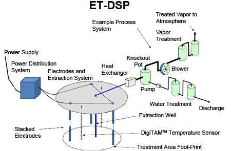
Figure 2. IST Treatment using ET-DSP system design.
The soil overburden consists of heavily stratified loam, sand, clay, sandy gravel, silty sand, and till. A 2006 chemical oxidation pilot test was unsuccessful due to the heterogeneous nature of the soil and sorption of VOCs to the fine-grained component. IST treatment was then selected with the expectation that heating subsurface soil to temperatures near the boiling point of water could mobilize and facilitate the removal of NAPL. The ET-DSP process chosen involves heating saturated and unsaturated zone soil by passing an electrical current between underground electrodes; groundwater and saline are simultaneously circulated past the electrodes to transfer heat by convection. The heat volatilizes the VOCs trapped in the subsurface, generating soil vapors and steam which are extracted and treated prior to discharge to the environment. Figure 2 shows the basic design of IST treatment using the ET-DSP process.
IST treatment was conducted from 2010 to 2011. The goal was to reduce TCE concentrations in soil and overburden groundwater to the point of diminishing returns in order to eventually reach the site cleanup goals of 77 µg/kg for soil and 5 µg/L for groundwater. Treatment depth ranged from the ground surface to the bedrock, which is approximately 45 feet below ground surface (bgs). Figure 3 provides an overview of the treatment area.
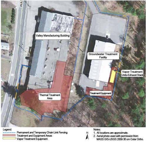
Figure 3. Aerial view of the thermal treatment area.
The IST system was designed to raise the temperature of soil and groundwater to 90°C and 100°C, respectively. Water and saline were injected to enhance the thermal process. Heat exchangers, a cooling tower, and a chiller were used to cool extracted vapors. Moisture knockout tanks removed liquids from the recovered vapors and steam; the vapors were then treated using granular activated carbon prior to release into the environment. Liquids extracted from the subsurface via pumping were cooled in heat exchangers, while bag filters were used to remove entrained sand and grit. NAPL was separated using an oil-water separator, and the recovered water was sent to the onsite groundwater treatment facility. A vapor cover was installed over the thermal treatment area to prevent rainwater and snowmelt infiltration and to provide a surface seal for effective vacuum extraction of vaporized contaminants.
Six different types of wells were constructed within the treatment area: 40 standard electrode wells (10-inch diameter soil boring), 24 mini-electrode wells (6 5⁄8-inch diameter soil boring) to supply electrical current beneath the plant building, 29 SVE wells (2-inch steel casing) to recover vapors from the unsaturated zone 2-12 feet bgs, 15 multi-phase extraction wells (4-inch diameter steel casing with stainless steel screen to maintain pneumatic and hydraulic control and extract liquid and vapor from the unsaturated and saturated zones), 16 temperature sensor wells placed in 3-foot depth intervals from the ground surface to approximately 10-45 feet bgs, and 12 temperature, pressure, and vacuum sensor wells to monitor subsurface temperatures as well as water pressure and vacuum for hydraulic and pneumatic control. A total of 143 electrodes were installed within the treatment area, with 1 to 3 electrodes installed in each electrode well, depending on the depth of the treatment zone. After startup, the system was modified by adding 12 shallow steam injection wells to obtain more heat and ensure the cleanup goals would be reached.
About 17,450 cubic yards of soil in a 4,830 square-foot area were treated. Forty-two of the 44 confirmation soil samples collected in April 2011 indicated TCE concentrations below the soil cleanup goal. TCE was detected at concentrations of 5,600 µg/kg (23 to 25 feet bgs) and 7,000 µg/kg (3 to 5 feet bgs) in two areas of the vadose zone below a paved portion of the site. However, an overall reduction of TCE concentrations by 65-72% was achieved in these areas.
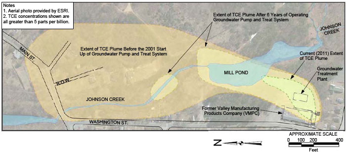
Figure 4. A 95% reduction in the area of the VOC plume was observed between 2000 and 2011.
Groundwater sampling in April and December 2011 indicated a 97% overall reduction of TCE. TCE concentrations were below the cleanup goal in 16 of the 19 wells sampled in April and in 19 of the 23 wells sampled in December. The majority of the samples had less than or equal to 1 µg/L TCE. In addition, the size of the TCE plume has decreased by approximately 95%, from 36 acres in 2000 to 1.8 acres in 2011 (Figure 4). This trend is expected to continue due to significant contaminant reduction by IST treatment, continued operation of the P&T system (at 55 gallons per minute), and continued natural attenuation of contaminated groundwater downgradient of the source area. Additional groundwater monitoring by MassDEP is planned for fall 2012.
During its 192 days of operation, the IST treatment system removed over two million gallons of water and condensate, 311 million cubic feet of non-condensable vapors, and 1,300 lbs of VOCs (including over 18 gallons of NAPL). The system used approximately 2,422 kilowatt-hours per day. The overall cost of IST treatment is estimated at $6,264,000, with over half dedicated to design, construction, operation and maintenance, and demobilization. Remaining costs included electricity, field assessments, laboratory analyses, labor, oversight, and other administrative costs. Per unit treatment cost is estimated at $359 per cubic yard of soil.
RESOURCES
CLU-IN Website:
- Thermal Treatment: In Situ: This remediation technology area of CLU-IN provides an overview and compendium of guidance materials, application reports, and training or other tools for designing, installing, and monitoring IST systems.
- In Situ Thermal Treatment Site Profile Database: The U.S. Environmental Protection Agency (EPA) Technology Innovation and Field Services Division sponsors this database of site-specific profiles involving IST technologies in past field demonstrations or full-scale applications. The database currently contains 152 profiles.
Green Remediation BMPs: Implementing In Situ Thermal Technologies
The latest in EPA's series of quick-reference fact sheets on best management practices (BMPs) for greener cleanups focuses on implementing IST technologies (EPA 542-F-12-029).The BMPs involve use of processes, equipment, and analytical tools that can be used to reduce the environmental footprint of applying these technologies, which typically involves significant rates of energy consumption. Along with strategies to conserve energy, the BMPs address other core elements of a greener cleanup: reducing air pollutants and greenhouse gas emissions, reducing water use and negative impacts on water resources, improving materials management and waste reduction efforts, and protecting ecosystem services.
Technical Report: In Situ Thermal Treatment of Chlorinated Solvents: Fundamentals and Field Applications
This report (EPA 542-R-04-010) from the U.S. EPA Office of Superfund Remediation and Technology Innovation contains information about the use of IST technologies to treat chlorinated solvents in source zones containing free-phase contamination or high concentrations of contaminants that are either sorbed to soil or dissolved in groundwater in the saturated or unsaturated zone.
Cost & Performance Case Studies: Thermal Treatment (In Situ)
The Federal Remediation Technologies Roundtable maintains a searchable database currently containing 26 case studies on remediation demonstration projects involving IST as the primary technology.
Contact Us:
Suggestions for articles in upcoming issues of Technology News and Trends may be submitted to
Linda Fiedler via email at fiedler.linda@epa.gov.
Past Issues:
Past issues of the newsletter are available at http://www.clu-in.org/products/newsltrs/tnandt/.
Archives | Subscribe | Change Your Address | Unsubscribe


