Ground Water Currents, March 1998, Issue No. 27
Contents
Air Sparging/High Vacuum Extraction to Remove Chlorinated Solvents in Ground Water and Soil
1,200-Foot Permeable Reactive Barrier in Use at the Denver Federal Center
EPA Releases Monitored Natural Attenuation Directive
New Phytoremediation Report Issued
Technology Vendor Opportunities
Air Sparging/High Vacuum Extraction to Remove Chlorinated Solvents in Ground Water and Soil
by Jim Phelan, U.S. Department of Energy, Sandia National Laboratories
Two technologies—air sparging coupled with high vacuum extraction—are expediting the cleanup of both ground water and soil at the U.S. Department of Energy’s (DOE’s) Mound facility in Miamisburg, Ohio. In 1995, DOE and EPA had selected pump and treat as the baseline remedy for contaminated ground water. Although hydraulic containment was achieved with the pump and treat system, the system proved limited in its ability to clean up the aquifer expeditiously. For this reason, an air sparging (AS) system was installed to remove dissolved phase contaminants in the ground water and a high vacuum soil vapor extraction (SVE) system was installed to remove source contaminants in the vadose zone.
The southwestern portion of the Mound Facility, which is a former nuclear weapons component research and manufacturing facility, is located directly above the eastern flank of a sole source aquifer that provides drinking water to a large population. In this locale, the aquifer is shallow (20 feet below ground surface) and characterized as highly permeable sand, silt, and gravel. As a result of past activities at the facility, a small portion of the aquifer has been contaminated with various chlorinated solvents. Remediation of this two-acre area (known as Operable Unit 1) is complicated further by a landfill located over a portion of the site.

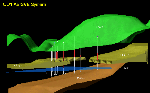
The blue plane represents the water table elevation at 680
feet. Long well traces below
the water table are sparge wells, and the shorter well traces above the water
table are soil vapor
extraction wells. The break in the till layer is due to past excavation
activities.
The large topographic feature in the upper right is an engineered sanitary
landfill that was constructed in the late 1970's.
The major ground water contaminants include trichloroethene (TCE), tetrachloroethene (PCE), and 1,2-cis-dichloroethene (DCE), with average concentrations in the tens of parts per billion (ppb) for each contaminant, and highest concentrations of 200, 300, and 600 ppb, respectively. Vinyl chloride also is present in average concentrations of a few ppb, and up to 50 ppb in certain locations. In addition, unanticipated concentrations (up to 220 parts per million) of toluene were identified during early operation of the system.
Soils overlying the aquifer include complex lenses of glacial till, silts and sands, and fill material, and contain the same contaminants as detected in the ground water (typically in the 100 ppb range but up to 300 ppm in isolated areas). Past activities have disturbed the entire area, resulting in a heterogeneous distribution of both soil type and contaminant concentration.
During pilot tests completed in 1996, approximately 13 pounds of total volatile organic compounds were removed from an extraction well (not screened within the till unit), operating over a four-day period at a steady air flow rate of 80 standard cubic feet per minute (scfm) with 13 inches of mercury vacuum at the well bore. A screened extraction well within the low permeability till unit resulted in very low mass removal, with steady flow at around 4 scfm and with 24 inches of mercury vacuum at the well bore. Air sparging in the permeable sand and gravel produced an approximate radius of influence of 20 feet at a flow rate of 20 scfm.
Pilot test data were used to select an appropriate spacing for the AS/SVE wells. The heterogeneous nature of both the contaminant distribution and permeability within the overlying soils provided a challenge in selecting an optimal screen location for the SVE wells. Where contaminated glacial till existed, it was important to ensure the SVE well was screened only within the low permeability till and did not extend into a horizon of higher permeability. Conversely, it was appropriate to utilize a relatively long-length screen where till was absent.
Field samples were taken during installation of the AS/SVE system to determine the presence of the till unit, location of the till outwash contact, and the three-dimensional distribution of contaminants. Based on field analysis of these samples, SVE screen intervals providing for optimal mass removal at each wall were identified.
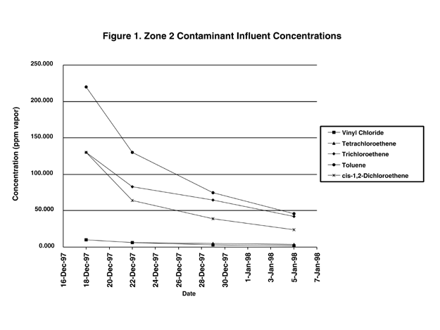
Preliminary results from the system have shown that approximately 450 pounds of contaminants have been removed from the soils in the first six weeks of operation. Figure 1 shows concentrations of several of the principal contaminants over time. During the next several months, investigators will monitor the system to determine its effectiveness in mass removal and its effect on the ground water containment system (pump and treat).

This demonstration is sponsored by the Innovative Treatment Remediation Demonstration (ITRD) Program coordinated by the U.S. Department of Energy’s (DOE’s) Sandia National Laboratories. The ITRD is a public-private partnership among DOE, Clean Sites, Inc, and EPA with the goal of reducing barriers to the use of new technologies. Through the ITRD Program, advisory groups composed of DOE, EPA, private industry, and regulatory agency representatives were established to work on this project in conjunction with the DOE Mound Facility Environmental Restoration Program.
For more information, contact Jim Phelan (DOE/Sandia National Laboratories) at 505-845-9892, Mike Hightower (DOE/Sandia National Laboratories) at 505-844-5499, or Mark Gilliat (Babcock and Wilcox of Ohio) at 937-865-4407.
1,200-Foot Permeable Reactive Barrier in Use at the Denver Federal Center
by Alex Caruana, State of Colorado, Department of Health and Environment
An in situ ground water treatment system was installed in the Fall of 1996 at the Denver Federal Center (DFC) to minimize the off-site migration of ground water contaminated with halogenated volatile organic compounds.
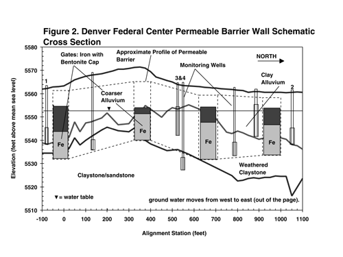
The 1,200-foot barrier consists of iron sheet-pilings driven across the aquifer perpendicular to the direction of ground water flow, acting as an underground dam. Contaminated ground water is funneled through four 40-foot-wide aperatures, or “gates” in the barrier, containing iron filings. The iron filings are capable of chemically degrading dissolved chlorinated hydrocarbons in the ground water. The DFC “funnel and gate” system is illustrated conceptually in Figure 2.

The dimensions of each gate were varied based on modeled ground water flow velocities. In the direction parallel to ground water flow, the basic design for each gate consists of a gravel-iron-gravel sandwich capped by a bentonite plug to below the water table, such that ground water flows into each gate through two feet of gravel before entering the iron treatment zone. After passing through the iron, ground water exits through another two feet of gravel. Iron thicknesses parallel to ground water flow direction were six feet, four feet, two feet, and two feet. Iron thicknesses were varied to account for varying contaminant concentrations and ground water flow velocities along the length of the barrier. Total volume of iron used on the project was approximately 6,800 feet3 (2,880 feet3 in gate 1; 2,400 feet3 in gate 2; 880 feet3 in gate 3; and 640 feet3 in gate 4).
In addition to the chemistry of the zero valent iron reduction process, the geology of the aquifer plays a critical role in the application of this technology. At the DFC, the aquifer consists of three lithologic units of decreasing permeability with depth: alluvium, weathered claystone, and hard claystone. In order to achieve maximum containment, the base of the system should be keyed into the unit with the lowest permeability; at the DFC, this unit is the hard claystone. At the north end of the DFC system, however, the driving of sheet-piling to this horizon (a depth greater than 45 feet) was not feasible. This situation is mitigated by a decrease in transmissivity (aquifer thickness x hydraulic conductivity) in the alluvium to the north, as it transitions from sand and silt in the south to increasing clay northwards. Also, ground water contamination had not been observed at significant levels at the northern end of the barrier.
Trichloroethene (TCE), 1,1-dichloroethene (DCE), and 1,1,1-trichloroethane (TCA) at concentrations on the order of hundreds of parts per billion are present in the aquifer upgradient, (west) of the barrier. In passing through the iron filings, all contaminants (with the exception of 1,1-dichloroethane, which persists at concentrations of a few parts per billion) are reduced to non-detect levels in the treatment cells or “gates.”
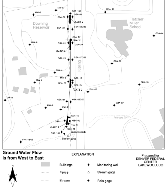
Twin monitoring wells, screened to monitor vertical gradients between the alluvium and the underlying confining layers, were located at points midway between the treatment cells (“3 & 4” in Figure 2) [corresponding to well pairs GSA-23,22D; GSA-28,27D; GSA-33,32D on the site map provided in the Internet version of this newsletter]. Additional monitoring wells are located in the treatment cells.

Site Map for the Denver Federal Center
Wells 1 and 2 are located to monitor for by-pass at either end of the permeable barrier wall [corresponding to GSA-18a and 19a on the site map]. As of the latest monitoring event (November 1997) elevated concentrations of TCE, DCE, and TCA in well 18a (the well at the south terminus of the barrier) indicate that some by-pass has started to occur. At this time, some downgradient wells have shown significant decreases in concentrations for specific contaminants. Other wells that generally are further downgradient, however, have yet to show significant decreases in contaminant concentrations after one year of operation. Some underflow also is being observed at one of the four gates [Gate 2 on the site map]. Remedies to these situations currently are being evaluated and should be implemented within six months.
The General Services Administration and Federal Highway Administration jointly undertook this project in response to an April 1996 compliance order from the State of Colorado’s RCRA program. Today, the DFC is in many respects a research campus whose major tenants are more than 23 different federal agencies. The DFC was formerly a U.S. Department of Defense munitions site called the Denver Ordnance Plant.
Use of this zero-valent iron treatment technology is planned or in place at other facilities in Colorado, including the U.S. Department of Energy’s Rocky Flats Environmental Technology Site near Denver and Colorado Crystal in Loveland. For more information, contact Alex Caruana (State of Colorado) at 303-692-3340, Kevin Phillips (General Services Administration) at 303-236-7131 extension 232, Rick Cushing (Federal Highway Administration) at 303-716-2138, or Peter McMahon (U.S. Geological Survey) at 303-236-4882 extension 286.
GWRTAC Updates
Technology Evaluation Report: Phytoremediation
The Ground-Water Remediation Technologies Analysis Center (GWRTAC) recently
issued this technology evaluation report discussing the current status of
phytoremediation for treating soils and ground water, as well as the economics,
regulatory requirements, and limitations of the technology. Readers may
download the report at no cost from GWRTAC’s Internet site at
http://www.gwrtac.org, or contact
GWRTAC at 800-373-1973 for more information.
Technology Evaluation Report: Remediation of
Metals-Contaminated Soils and Groundwater
GWRTAC issued this technology evaluation report to address the persistent
problem of metals contamination at many hazardous waste sites. The report
presents several field demonstration summaries (including information such as
compounds treated, site characteristics, project results, participants, and
contacts) and describes the current status of existing technologies for
treating metals-contaminated soils and ground water. This evaluation report and
additional information on ground-water remediation also may be downloaded from
GWRTAC’s Internet site.
EPA Releases Monitored Natural Attenuation Directive
In December 1997, EPA issued the interim final directive, Use of Monitored Natural Attenuation at Superfund, RCRA Corrective Action, and Underground Storage Tank Sites. This directive clarifies EPA’s policy regarding the use of monitored natural attenuation for remediation of contaminated soil and ground water at sites regulated under all programs that are administered by EPA’s Office of Solid Waste and Emergency Response (OSWER). The document (OSWER Directive #9200.4-17) may be downloaded from the Internet at http://www.epa.gov/swerust1/directiv/d9200417.htm. Paper copies of the document are available from EPA’s RCRA, Superfund, OUST, and EPCRA Hotline at 800-424-9346 or 703-412-9810.
New Phytoremediation Report Issued
Phytoremediation of TCE in Groundwater Using Populus was prepared under grant for EPA by Jonathan Chappell, a National Network of Environmental Management Studies fellow. The publication provides a basic understanding and current status of phytoremediation for shallow groundwater. The report may be downloaded from the Internet at http://clu-in.org/techpubs.htm.
Technology Vendor Opportunities
Site Characterization and Field Analysis Technology
Verification
Over the next few months, the Environmental Technology Verification (ETV)
Program will offer several opportunities for site characterization and field
analysis technology vendors to participate in the ETV’s Consortium for
Site Characterization Technology (CSCT) verification program, including a call
for vendor interest.
For more information, check CSCT information posted on the ETV’s Internet site, www.epa.gov/etv, or the Hazardous Waste Cleanup Information System at clu-in.org. Also, subscribe to EPA’s “TechDirect” technology information service to receive a monthly e-mail message on new developments and publications related to remediation and site characterization/field analysis technology.
Calendar
| Advances in Innovative Ground Water Remediation Technologies Conference GWRTAC and EPA’s Technology Innovation Office will co-sponsor a one-day conference on May 6, 1998, at the Cathedral Hill Hotel, San Francisco, CA. Anticipated technical sessions will address topics such as natural attenuation, phytoremediation, treatment walls, and remediation of dense non-aqueous phase liquids. For agenda information and a registration form, contact GWRTAC at the Internet site http://www.gwrtac.org or by calling 800-373-1973. To register, e-mail karen_devlin@philip-serv.com or call 215-643-5466. |
| We now offer a new service-TechDirect-to keep you abreast of new EPA publications and event of interest to site remediation and site characterization professionals. Once a month, a TechDirect message will be sent via email describing new products and instructions on how to obtain them. |


