![]() A newsletter about soil, sediment, and groundwater characterization and remediation technologies
A newsletter about soil, sediment, and groundwater characterization and remediation technologies
- Cape Cod Wind Resources Provide Energy for Long-Term Groundwater Cleanup at MMR
- Gas-to-Energy System at Former Landfill Generates Power for Gas and Leachate Treatment Systems
- Solar-Powered Recirculation Accelerates Bioreactor Operations at Travis AFB
- Program Expands for Upcoming Green Remediation Conference
- Partnering for LFG Energy
This issue of Technology News and Trends highlights site remediation projects using onsite renewable energy resources to power treatment systems or to offset the air emissions and costs associated with consuming electricity generated by conventional power plants. Highlighted projects include both large- and small-scale systems producing power from wind, landfill gas, and solar resources.
Cape Cod Wind Resources Provide Energy for Long-Term Groundwater Cleanup at MMR
CLU-IN Resources
Other applications of renewable energy for site
cleanup are described in site-specific profiles
and reports available online at CLU-IN's Green
Remediation Focus (www.cluin.org/
greenremediation). In addition, information about
developing renewable energy on currently or
formerly contaminated land is offered online by
EPA's RE-Powering America's Land Initiative
(www.epa.gov/renewableenergyland).
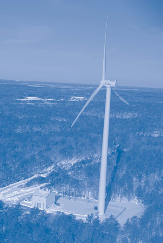
The Air Force Center for Engineering and the Environment (AFCEE) recently began operating a 1.5-MW wind turbine to power ongoing remedial actions at the 22,000-acre Massachusetts Military Reservation (MMR) on Cape Cod, MA. The wind turbine is expected to meet 25-30% of the total energy demand of remediation systems treating approximately 14.5 million gallons of contaminated groundwater per day. AFCEE anticipates capital expense payback for the $4.6 million turbine in six to eight years.
MMR has been used since 1911 for military training and aircraft operation and maintenance. Historical activities involved use of hazardous materials such as explosives, fuels, and cleaning solvents that were released to the environment. Contaminants of concern and highest concentrations during 2009 in the 12 remaining groundwater plumes include trichloroethene (TCE, 1,740 µg/L), tetrachloroethene (51 µg/L), carbon tetrachloride (17 µg/L), and ethylene dibromide (23 µg/L).
The site is located over a recharge area for the Sagamore Lens, a sandy, 300-foot-thick sole-source aquifer. Most of the contaminant plumes migrated beyond the base boundary and threatened drinking water wells in surrounding towns. Several discharged to freshwater bodies or nearby ocean harbors. The largest plume is nearly four miles long, over one mile wide, more than 100 feet thick, and 100-300 feet deep.
Remediation of the site's source areas has been completed through removal actions or in situ air sparging/soil vapor extraction and thermal treatment. To address groundwater contamination, AFCEE installed 105 extraction wells with 27 miles of pipeline and constructed nine treatment plants to treat extracted groundwater through granular activated carbon (GAC) media. Treated water is returned to the aquifer through reinjection wells and infiltration trenches or discharged to local rivers. An optimization program initiated in 2003 determined that the existing treatment systems collectively consumed 12,300 MWh of electricity each year, all of which was supplied by conventional power plants. This "upstream" power production was estimated to annually emit over 6.7 tons of carbon dioxide, 11,833 pounds of nitrous oxides, 11,443 pounds of sulfur dioxide, and 418 pounds of particular matter. Economic analysis revealed that this amount of electricity, purchased at a rate of $0.167 kWh, cost MMR over $2 million each year.
In 2006, to offset the air emissions and costs, AFCEE assessed wind turbine constructability by evaluating the economic, design, and environmental factors affecting potential generation of electricity onsite. Results indicated that, due to net metering under the Massachusetts Green Communities Act, transfer of wind-generated electricity to the local utility in exchange for credit on electricity purchases offered the greatest economic advantage. Initial funding was available through the Defense Environment Restoration Account and a $300,000 renewable energy grant from the Massachusetts Technology Collaborative.
Design analysis indicated that a 260-foot turbine hub height with a 253-foot-diameter rotor would maximize wind capture. Together, the system's three 123-foot rotor blades would sweep an area of approximately 50,676 square feet. Selection of blades made of epoxy and fiberglass provided durability while minimizing weight and increasing system efficiency.
The system was designed to operate at a "cut-in" wind speed as low as 6.7 mph and suspend operation at a "cut-out" wind speed of 45 mph, which accommodated the area's average wind speed of 14.6-15.8 mph at a 260-foot height. System design called for turbine survival at wind speeds reaching 134 mph. A maximum power output of 1,500 kW would be achieved at a wind speed ranging from 25 mph to the cutout speed.
Preferential siting factors included sufficient open space to minimize interference from nearby structures and close proximity to an existing 23-kV power line for interconnection. Based on the design specifications and analysis of site conditions, an area of higher elevation along the southwestern boundary of MMR property was identified as the optimal location. Use of an existing cleared area behind the treatment plant at this location would avoid destruction of vegetation and minimize ecosystem disruption. Turbine siting near an operating plant also allowed for streamlined monitoring and maintenance.
A 2007 environmental assessment completed under National Environmental Policy Act requirements found that the proposed project would pose no significant impact on wildlife or other natural resources. Clear visibility of the proposed turbine from certain areas was predicted within a 6.7-mile radius. Much of this visibility was from Buzzards Bay or would be blocked by terrain or seasonal forest cover.
Noise assessment predicted a level of 65 dBA at the turbine tower base, which is below the 85 dBA eight-hour threshold set by the National Institute for Occupational Safety and Health. Estimated noise levels decreased to less than 40 dBA on the perimeter of the closest residences and to less than 35 dBA at the edge of sensitive ecological environments extending to the bay. Other environmental factors included potential disruption to aviation patterns and radar equipment used by onsite and nearby facilities operated by the U.S. Air Force, Otis Air National Guard Base Airport, U.S. Coast Guard, and Camp Edwards. The Federal Aviation Administration and base facilities determined the proposed wind turbine would not significantly impact their mission or activities, and the U.S. Air Force Space Command found no problems related to radar use.
Studies indicated that resident and migratory birds tend to forage in nearby pine forest habitats, rather than on bare ground of the proposed turbine site, and that the proposed site contains no unique habitat features likely to funnel bids through the turbine rotor-sweep zone. The studies also considered results of a recent literature review that found bird fatalities caused by turbine collision across the United States have been low, averaging 2.3 birds per turbine per year. Assessment of effects on other wildlife concluded that potential impacts on two species of concern (the eastern box turtle and New England cottontail) during construction would be minimized by best management practices such as installing silt fencing and performing daily site inspections.
Field preparations for the wind turbine began in late 2008, following nearly two years of approval and planning activities. In March 2009, approximately 600 yd3 of 5,000-psi concrete were laid to form a foundation 57 feet wide and 3-8 feet high, meeting specifications that included a load-bearing capacity for the selected 37-ton rotor and 73-ton generator. Detailed coordination was needed to transport turbine components from various manufacturers as far away as Germany and North Dakota.
By the end of October 2009, construction was complete (Figure 1). Turbine operations that began in early December 2009 are expected to produce 3,810 MWh each year, based on a 29% capacity. During the initial two months of operation, the turbine produced approximately 602 MWh of electricity, which represents an electricity purchase savings of $100,000.
Turbine installation did not impact MMR remedial work. Operation and maintenance (O&M) includes weekly visual inspections by the turbine installer and semiannual maintenance by the turbine manufacturer to ensure proper torque, lubrication, and working order of components. Onsite staff can access continuous monitoring data, while comprehensive monitoring and control is provided remotely by the manufacturer's control center in Germany.
The expected lifespan of the new turbine is 25 years, although groundwater remediation in some areas of MMR may continue over the next 50 years. As a result, AFCEE plans to investigate potential installation of two or three additional wind turbines to fully offset power used by the treatment systems and an ongoing Army Impact Area Groundwater Study Program.
Contributed by Rose Forbes, AFCEE/Otis Air National Guard Base (rose.forbes@us.af.mil or 508-968-4670)
Gas-to-Energy System at Former Landfill Generates Power for Gas and Leachate Treatment Systems
Since 2002, the U.S. Environmental Protection Agency (EPA) Region 9 has deployed a system for converting landfill gas (LFG) to electricity at the Operating Industries, Inc. Superfund site (OII) in Monterey Park, CA. The system relies on a network of microturbines that generated sufficient electricity upon startup to meet 70% of the site's remediation needs. Substitution of conventionally-generated electricity with the onsite renewable energy saves an average of $250,000 per year in energy costs for the project.
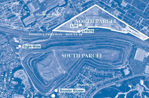
The OII site served as a municipal landfill from 1948 to 1984, amassing both residential and commercial wastes in a former quarry pit through cut-and-cover construction. Approximately 38 million cubic yards of municipal solid waste and up to 300 million gallons of liquid waste including a wide range of hazardous waste accumulated at the 190-acre landfill. The Pomona Freeway now splits the site into two parcels (Figure 2) with different terrain and waste thicknesses, which are estimated at 200-325 feet in the south parcel and up to 55 feet in the north parcel. Observation of leachate seeping offsite in 1982 led to the construction of a leachate collection system and ultimate closure of the landfill in 1984.
Remedial investigations found that elevated concentrations of hazardous substances in both leachate and LFG at OII were migrating to surrounding soil, groundwater, surface water, and ambient air. The selected remedy involved construction of LFG and leachate collection systems, stormwater collection ponds, and cover systems. The LFG collection system comprises 460 gas extraction wells, including 185 dual-phase extraction wells, and transmission lines to prevent lateral and upward migration of LFG. The landfill gas treatment system (LFGTS) consists of two thermal oxidizers with a continuous emission monitoring system. The oxidizers operate at 1,800°F, achieving a 99.99% destruction rate efficiency for contaminants (primarily volatile organic compounds) prior to air release.
In 2001, when the retail rate for electricity increased OII's annual treatment costs to $370,000, Region 9 determined that significant savings could be achieved using some of the LFG as a renewable energy source to directly power the treatment systems rather than treating it for air release. Microturbines were selected for electricity generation to accommodate the LFG methane content, which was lower than typically needed to operate internal combustion engines conventionally used for gas-to-energy systems but high enough to meet more than half of the energy demand. Microturbine operations also were expected to result in lower rates of nitrogen oxides production and were more compatible with the smaller LFGTS at OII. The total energy demand of the treatment systems was estimated at 600 KWh.
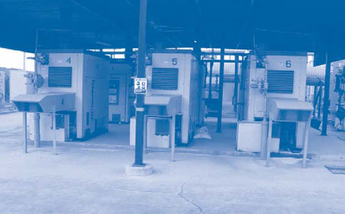
Six 70-kW Ingersoll-Rand PowerWorks microturbines (Figure 3) were installed at the north parcel in 2002. The units are equipped with onboard compressors that pressurize the LFG to 15 psig to remove moisture. Because the power output of microturbines is greatest at cool ambient temperatures, the compressed LFG is chilled to 40°F with a refrigeration system and then reheated to 65°F by a heat exchanger.
LFG from the south parcel is transferred to the treatment system by way of a six-inch dedicated transmission line running through a bridge over the Pomona Freeway. Extracted LFG from the combined parcels is monitored for methane concentration, temperature, gas flow, pressure, and oxygen content through use of a continuous gas quality analyzer. Since the microturbine exhaust has an oxygen content and temperature compatible with the LFGTS, the exhaust stream is routed directly to the LFGTS combustion air blowers for treatment by thermal oxidizers to destroy remaining offgases. The system currently extracts LFG at an average rate of 4,200 scfm and with an average methane content of 21%.
Microturbine purchasing costs (including equipment, installation, and warranty) totaled $1.25 million, which was reimbursed in part by a $450,000 energy grant from Southern California Edison and a $105,000 energy rebate from the California Energy Commission. Annual operating costs for the microturbines averaged $10,000 during the five-year warranty period and now average $25,000 for labor, parts, and repairs. To date, the system has generated more than 15,000 MWh of electricity, which is equivalent to an energy cost savings of nearly $21,000 for the project each month or approximately $1.75 million over seven years of operation. Cumulative net project savings are conservatively estimated at $647,000, based on 2006/2007 energy production rates.
LFG methane content over the eight years of microturbine operation has ranged from 29 to 39%—somewhat higher than the 25% used in project design. Initial capacity of the microturbines to meet 70% of the treatment system's total energy demand has decreased to 50% over time due to reduced equipment efficiencies caused by aging and frequent repairs. The capacity is expected to decline further as LFG begins to gradually diminish. As a result, EPA plans to replace the six microturbines with next-generation turbines having a combined capacity of 500 kW and capability to generate power from LFG with lower methane content.
In 2006, a 6-foot monocover (primarily clay) and geosynthetic clay liner cap were completed on the south parcel to minimize percolation of liquids into the waste, improve slope stability, and provide erosion and gas migration controls. A companion leachate collection system and a leachate treatment plant (LTP) collects the landfill liquids for treatment through processes such as GAC adsorption, chemical precipitation, air stripping, and sand filtration. In addition, construction of a perimeter liquids control system (PLCS) to control offsite leachate migration is nearly complete. The LTP has treated approximately 4.5 million gallons each year since 2000 and will annually treat up to 10 million gallons when the PLCS fully operates. EPA anticipates future sale of the treated liquids for irrigation of neighboring agricultural and cemetery properties.
Construction of a similar cap began two years ago on 10.5 acres west of the north parcel. Upon capping completion, the entire 45-acre north parcel (excluding the LTP and LFGTS treatment facilities) will be redeveloped as a retail marketplace. Ongoing exploration of the site's redevelopment potential and long-term energy needs has prompted EPA to explore other renewable energy sources at OII. For example, the onsite thermal plumes could provide up to 48 MBTU/hr of energy for combined heat and power available to the LFGTS building or future businesses on the north parcel. Other opportunities include leasing of 50 level acres on the south parcel for development of a solar energy farm.
Contributed by Shiann-Jang Chern, Ph.D., EPA Region 9 (chern.shiann-jang@epa.gov or 415-972-3268)
Solar-Powered Recirculation Accelerates Bioreactor Operations at Travis AFB
AFCEE and Travis Air Force Base (AFB) have partnered to demonstrate an in situ, solar-powered bioreactor for treating residual contamination at the base's Site DP039 near Fairfield, CA. The system was installed in 2008, following seven years of dual-phase extraction treatment that reduced TCE and daughter product concentrations in groundwater from 20,000 ppb to asymptotic values of 300-400 ppb. Following 12 months of bioreactor operation, performance evaluations indicate that the new treatment system has reduced TCE concentrations in source area groundwater an additional 75%.
Until the late 1970s, vehicle and aircraft maintenance at Site DP039 involved use of a battery acid neutralization sump. Investigations indicated that unauthorized disposal of cleaning solvent in the sump had created a TCE plume extending over 1,500 feet downgradient of the source. The confirmed TCE source encompassed an area approximately 20 by 20 feet and extending 40 feet below ground surface (bgs). Source area and surrounding soil consists of layered silts, clays, and sands with an average hydraulic conductivity of 10-4 to 10-5 cm/s. Depth to groundwater is 25 feet bgs.
Design of the bioreactor was based on a first-generation system implemented in 2003 at Altus AFB, OK. The second-generation design used at Travis AFB includes a deeper excavation and addition of iron pyrite to stimulate chemical reduction of TCE and daughter products. Construction of the bioreactor began in early November 2008. Field preparations included clearing a concrete and steel vault used by the past dual-phase extraction system, which employed two extraction wells. One well was targeted for use in bioreactor recirculation, and the second was preserved for performance monitoring. Approximately 300 yd3 of soil were excavated from the former sump area. Of this, 20 yd3 required disposal at an offsite hazardous waste disposal facility, and the remainder was deemed suitable for on-base fill material.
A conventional excavator was used to dig a trench 20 feet long, 20 feet wide, and 20 feet deep. As excavation progressed, a square trench box was installed to prevent sidewall collapse. A mixture of 45% gravel, 50% mulch, and 5% iron pyrite was poured into the bottom five feet of the excavation. The gravel-and-mulch mixture was added in five-foot lifts, and each lift was sprayed with food-grade soybean oil.
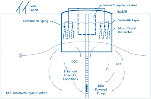
The completed bioreactor contains 150 yd3 of tree mulch that provides a long-term source of dissolved organic carbon (DOC) to create anaerobic conditions that support growth of contaminant-degrading bacteria. The mulch contains shredded branches gathered from fast-growing eucalyptus and other trees located in other areas of the base. Microbial growth and associated biological reductive dechlorination is enhanced by the 600 pounds of soybean oil serving as an additional source of soluble organic material.
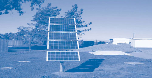
A 12-inch gap was left between the top layer of reactive material and the ground surface to provide space for an infiltration manifold consisting of perforated, one-inch-diameter PVC pipe to distribute pumped groundwater. The infiltration manifold was connected to the recirculation well and covered by a geotextile layer, and the trench was backfilled with 30 inches of clean soil (Figure 4). A 1/3-hp solar-powered pump was installed inside the former extraction well to capture contaminated groundwater from the aquifer and return it to the infiltration manifold overlaying the bioreactor.
Based on data from the National Renewable Energy Laboratory, the annual photovoltaic (PV) solar resources at Travis AFB average 5.5 kWh/m2/day. A 250-watt PV array consisting of five 50-watt panels was used to supply variable direct current to the solar pump (Figure 5). The PV system has been generating sufficient power to achieve an average groundwater recirculation rate of 815 gallons per day.
Nine months after bioreactor startup, performance evaluation determined that addition of a soluble organic substrate was needed to create sufficient anaerobic conditions in the aquifer surrounding the bioreactor. Consequently, 1,200 pounds of fructose corn syrup were injected into the bioreactor to increase aquifer DOC to concentrations above the target of 20 ppm. Six weeks after fructose injection, average DOC levels in the surrounding aquifer increased from 6 mg/L to 9 mg/L. The most recent comparison of analytical results for groundwater entering and exiting the bioreactor indicates a 99% decrease in TCE concentrations and a 77% total reduction of TCE, dichloroethene, and vinyl chloride. Low production of vinyl chloride in the bioreactor, in the 1-4 ppb range, suggests that both biotic and abiotic reductions are occurring in the bioreactor. To date, the solar-powered treatment system has recirculated and treated 220,000 gallons of groundwater.
The total cost for design, regulatory approval, construction, and initial 30-month operation of the treatment system is estimated at $320,000. This includes $10,000 in capital expenses for the PV array and solar-powered pump. Return on investment for the PV array is anticipated in approximately 10 years as a result of purchasing less electricity. When no longer needed at Site DP039, the array may be reused at other locations. Project review also indicates that shutdown of the dual-phase extraction system when contaminant concentrations reached asymptotic levels annually saved approximately 30,000 kWh of electricity and avoided the associated emission of approximately 24 tons of CO2 equivalent.
Final evaluation of the demonstration, which was funded by AFCEE's Broad Agency Announcement Program, will be used to prepare a final record of decision in 2011. AFCEE also anticipates using the demonstration results to help design and build two additional solar-powered bioreactors at sites in Kansas and Washington.
Contributed by Lonnie Duke, Travis AFB (lonnie.duke@travis.af.mil or 707-424-7520) and Doug Downey, CH2M Hill (doug.downey@ch2m.com or 303-674-6547)
Program Expands for Upcoming Green Remediation Conference
Renewable Energy and Site Reuse is one of several program tracks at the Green Remediation: Environment, Energy, and Economics international conference to be held June 15-17 in Amherst, MA. Other program tracks offered at the conference, which is co-sponsored by EPA and the Environmental Institute, include:
- Understanding the environmental footprint
- Policy and regulatory considerations
- Quantifying the environmental footprint
- Environmental footprint mitigation
- Innovative technologies for green remediation, and
- Economic considerations.
To obtain more details or to register, visit the University of Massachusetts Amherst online at: www.umass.edu/tei/conferences/GreenRemediation/index.html.
Errata
In the December 2009 article "Vegetable Oil Emulsion Promotes Contaminant Degradation in Bedrock Groundwater," concentrations of all contaminants were erroneously printed in unit measures of "mg/L" rather than "µg/L."
EPA's Landfill Methane Outreach Program forms partnerships to help communities, landfill owners, utilities, and other stakeholders assess feasibility and find financing for projects involving recovery and use of LFG as an energy source. Learn more about the opportunities and access technical information and tools at: ww.epa.gov/landfill/basic-info/index.html#03.
