![]() A newsletter about soil, sediment, and groundwater characterization and remediation technologies
A newsletter about soil, sediment, and groundwater characterization and remediation technologies
Thermal Technology Tested for Contaminant Recovery
RevTech Conference Coming in July
The U.S. EPA’s Technology Innovation Office (TIO) is sponsoring a new conference that showcases smart assessment and cleanup strategies involved in site reuse and land revitalization programs. The RevTech conference will be held July 22-24, 2003, at the Pittsburgh Marriott City Center. Online registration and additional information is available at http://brownfieldstsc.org.
A research project on steam enhanced remediation (SER) for the recovery of dense non-aqueous phase liquid (DNAPL) from fractured limestone has been undertaken at the former Loring Air Force Base Quarry site in Limestone, ME. Participants in the project include the Maine Department of Environmental Protection, U.S. EPA/Region 1, U.S. EPA/National Risk Management Research Laboratory (NRMRL), and the Air Force Base Conversion Agency. The purpose of the research project is to determine if steam injection can be used to enhance the recovery of contaminants from fractured limestone.
A former quarry used for the disposal of more than 400 drums of spent solvents was selected for this research. The fractured rock system at the quarry is highly complex with three sets of fractures and several faults in or around the target area. While tetrachloroethene (PCE) is the main contaminant of concern, other solvents and fuel components also are present. Rock chip samples were extracted with methanol and analyzed by EPA Method 8260 to determine the contaminant distribution. The analytical results showed concentrations up to 100 mg/kg in fractures ranging from 10 to 100 feet below ground surface (bgs). Transmissivity testing done on 10-foot intervals showed that the area generally has very low permeability, ranging from 10-4 to less than 10-7 m2/sec. Interconnectivity testing showed that there is limited fracture connectivity between the eastern, middle, and western parts of the site.
Based on the characterization information obtained during the first part of the project, three boreholes forming a semicircle with a diameter of approximately 40 feet at the eastern side of the site were chosen for steam injection. Ten boreholes through the center of the system and in the western side of the site were used for extraction, producing an extraction system approximately 60 feet wide and 150 feet long. A system of 23 thermocouple wells and electrical resistance tomography (ERT) implemented from nine boreholes was used to monitor temperature and steam flow. The sparsely fractured, low-transmissivity nature of the site limited the amount of steam that could be injected; thus, three extraction wells that were not producing significant amounts of contaminants were converted to steam injection wells after 30 days of injection. Operational techniques such as injection pressures, air injection, and drawdown of ground-water levels to create pressure cycling were tested to determine their effects on injection and extraction rates. The total period of the injection was limited by the budget to 83 days followed by 7 days of extraction.
Daily effluent samples of both the vapor and aqueous phases showed that extraction rates initially were low and generally decreased during the first three weeks of the demonstration, much as would be expected during conventional pump and treat operation. Subsurface temperature and ERT monitoring indicated that the steam and hot water condensate followed rather narrow paths in the limestone, and that only a small fraction of the rock was heated to steam temperature. Even these small temperature increases, however, significantly increased the effluent concentrations in both the vapor and aqueous phases. Aqueous concentrations of gasoline range organics, diesel range organics, and volatile organic compounds (VOCs) increased by an order of magnitude and more during the demonstration. Vapor phase concentrations increased slowly while steam was injected, and concentrations jumped by more than an order of magnitude when the pressure in the subsurface decreased as steam injection ended. At the time the demonstration ended, effluent concentrations were continuing to increase.
Post-treatment sampling of ground water and rock chips from within the treatment area will be used to determine remaining contaminant levels. Ground-water samples from two angled boreholes that begin next to the treatment area and extend below it will be used to determine if contaminants were mobilized downward or horizontally. Although remediation was not taken to completion, the observed steam flow and removal mechanisms suggest that SER can more effectively increase the mass removal rate than traditional methods such as pump and treat or soil vapor extraction.
Contributed by Eva Davis, U.S. EPA/ORD (580-436-8548 or davis.eva@epa.gov)
SERDP and NRMRL Sponsor Field Test of Cosolvent-Enhanced DNAPL Removal
Searching Made Easier for Perchlorate Remediation Resources
TIO is compiling information on research and application of technologies used for cleaning up perchlorate-contaminated ground water. As part of its effort to advocate more effective, less costly approaches to site cleanups, TIO has made this information available through a single location on its CLU-IN web site at http://cluin.org/perchlorate. The compilation currently includes policy and guidance documentation, related web links, technical presentations, and over 30 studies and reports on perchlorate issues.
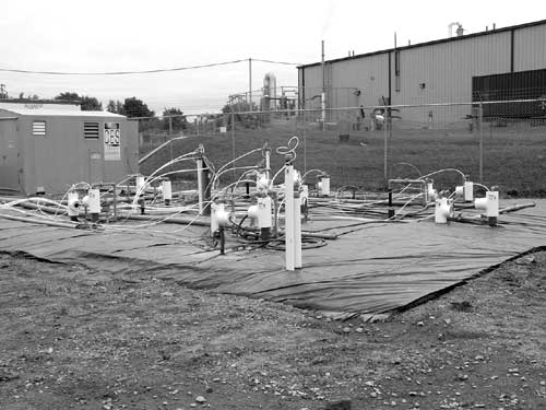
In July 2001, Clemson University and the U.S. EPA/NRMRL field tested cosolvent flooding for in-situ remediation of DNAPL source zones. The test was conducted at the Dover National Test Site (DNTS) at Dover Air Force Base, DE, as part of an enhanced source removal demonstration project funded by NRMRL and the Strategic Environmental Research and Demonstration Program (SERDP). Final test results estimated an 80% reduction in contaminant mass after 37 days of treatment.
The cosolvent flood test was performed in a 15-by-10-foot watertight cell lined by sheet-pile walls extending 45 feet bgs. The cell contained twelve 2-inch wells with 20-foot slotted screens and a 3-dimensional network of 108 small fluid samplers positioned at discrete vertical intervals below the water table, which was at 29 feet bgs. Site geology consists of unconsolidated Atlantic Coastal Plain sediments with interbedded sands, silts, and clays, and an average hydraulic conductivity of about 1 x 10⁻³ cm/sec.
Previous field testing of air sparging in this cell involved a controlled release of 66 liters (106.9 kg) of pure PCE. Air sparging removed approximately 58 liters (94.0 kg) of PCE, leaving a PCE residual of approximately 8 liters (13.0 kg). Prior to the flood test, an additional 48.9 liters (79.2 kg) of PCE were released to reach a total volume of 57 liters (92.3 kg). The PCE was released at a depth of 35 feet, producing a treatment zone extending from 35 feet bgs to the confining clay layer at 40 feet bgs.
The cosolvent flood consisted of a mixture of 70% n-propanol and 30% saltwater. Prior to mixing, a concentrated saltwater solution was prepared by adding 175 grams of food-grade calcium chloride dihydrate to each liter of water used in the mixture. Saltwater was selected as a component due to its very high density in comparison to water or propanol, and its associated capability to improve cosolvent delivery to lower parts of the aquifer. Saltwater also increased the partitioning of propanol into PCE, thereby decreasing density of the DNAPL and reducing its potential for downward mobilization during the flooding.
An initial non-reactive tracer test performed after the release revealed a distinct and isolated high permeability zone near the upper part of the saturated zone, which marginally reduced efficiency of the cosolvent flooding process. Ground-water samples collected from the extraction wells during the tracer test contained consistently high levels of dissolved PCE, with an average concentration of approximately 80 mg/L. The individual multilevel samplers had highly variable dissolved PCE concentrations, ranging from nearly zero to the point of PCE's aqueous solubility (about 160 mg/L).
Cosolvent flooding operated for a total of 37 days, at an average flow rate of 3.2 liters per minute. The cosolvent solution was recycled through air stripping and then reinjected. The flood used a total of 33,000 liters of 70% n-propanol and 30% water. Due to treatment and re-injection, 80,000 liters of remedial fluid were displaced through the test cell. Maximum PCE concentrations in the extraction wells ranged from 1,000 to 1,500 mg/L, or nearly ten times the normal aqueous solubility. No DNAPL or LNAPL was produced from the extraction wells.
Over the course of field testing, a total of 73.5 kg of PCE was extracted from the test cell (Figure 1). Post-treatment ground-water sampling of the extraction wells showed 80% lower dissolved PCE concentrations than before treatment, with an average PCE concentration of approximately 15 mg/L. NRMRL and SERDP are preparing a comprehensive summary of these demonstration results, as well as the results of other innovative DNAPL remediation technologies recently tested at the DNTS.
Contributed by A. Lynn Wood, U.S. EPA/ORD/NRMRL (580-436-8552 or wood.lynn@epa.gov) and Ronald Falta, Clemson University (864-656-0125 or faltar@clemson.edu)
Biosparging Used to Remove Chlorinated Solvents at the SRS Sanitary Landfill
As part of a comprehensive effort to address ground-water contamination at the U.S. Department of Energy Savannah River Site (SRS) near Aiken, SC, a biosparging system began operating in 1999 at the site’s sanitary landfill (SLF). Biosparging was selected to address the trichloroethene (TCE), vinyl chloride, and TCE breakdown products in the ground water underlying the landfill. By 2002, biosparging treatment had reduced ground-water concentrations of vinyl chloride and TCE within the treatment zone by 99% and 75%, respectively.
Large amounts of wastes were generated at the SRS during construction and operation of the facility. Cafeteria and office wastes, sewage sludge, miscellaneous construction materials, and debris routinely were disposed at the 70-acre unlined SLF from the early 1970s to the mid 1990s. After the discovery of ground-water contamination beneath the landfill, the main section and the southern expansion area of the landfill were covered with an engineered cap. Maximum concentrations of vinyl chloride and TCE at interior landfill wells were 480 µg/L and 31 µg/L, respectively, prior to biosparging treatment.
Three significant hydrogeologic units underlie the landfill: an uppermost unconfined aquifer, a confining unit, and a lower aquifer. The depth to the water table ranges from 30 ft to 60 ft bgs. Ground-water flow in the area of the landfill is primarily horizontal, with an upward flow component where it discharges to a large wetland adjacent to the landfill. Beneath the landfill, contaminants were identified only in the upper portions of the shallow aquifer. Numerical modeling estimates that the advective transport time from the main section of the landfill to a downgradient biosparging well between the landfill and wetland is 11 years, with another three years for discharge to the wetland (Figure 2).
Low dissolved oxygen levels observed after construction of the landfill cap suggested that reductive dechlorination of chlorinated compounds could occur beneath the landfill. Following successful field-scale testing of biosparging, a full-scale system was constructed. The system consists of two horizontal biosparging wells screened immediately below the vertical center of the contaminant plume: an 800-ft screened well downgradient of the landfill for treating TCE, and a 900-ft screened well side-gradient of the landfill for treating vinyl chloride. Each well consists of a six-inch-diameter outer steel casing, screen, and an inner four-inch, high-density, polyethylene liner. Both wells rely on a central air compressor unit (rated for a maximum airflow of 540 cfm) but operate independently to accommodate different injection configurations.
Optimization testing prior to full-scale operations demonstrated that additional nutrients were needed for the downgradient well area, while air injection was adequate for bioremediation in the side-gradient well area. Methane (0.7%) was injected into the downgradient well to stimulate growth of methane-oxidizing (methanotropic) organisms. These organisms produce the strong oxidizing agent (monooxygenase) needed for complete mineralization of TCE. As expected, methanotropic degradation of TCE was constrained to the sparging operation’s radius of influence (approximately 60 feet) but vinyl chloride degradation was found to occur wherever oxygen was present.
Methane injection was terminated in January 2001 because TCE concentrations had decreased substantially and numerical modeling predicted that the benefit of additional injection was limited.
Both wells currently treat vinyl chloride by serving as aerobic biodegradation pathways and by enhancing volatilization. Air is injected into the wells once every two weeks for 48 continuous hours at a rate of 220 scfm in the downgradient well and 250 scfm in the side-gradient well. After 24 hours, nitrous oxide and triethylphosphate nutrients (0.048% and 0.005% of total air/month, respectively) are injected in the downgradient well for 8 hours. Vinyl chloride concentrations have continued to decrease over the past year, with maximum concentrations during the first quarter of 2003 reaching 80 µg/L in an interior landfill monitoring well and 11 µg/L in a point-of-compliance well at the base of the landfill.
Ground-water models predict that primary contaminant concentrations will not exceed ground-water protection standards due to ongoing physical and biological processes of natural attenuation. Since concentrations have decreased to regulatory limits for this RCRA facility, plans are underway to suspend operation of the biosparging system and to continue ground-water monitoring for several years. Maintenance of the biosparging system will continue in the event monitoring results indicate that resumed operations are warranted. Additional information regarding enhanced bioremediation and monitored natural attenuation at the SRS SLF is available on-line at http://www.srs.gov/general/pubs/fulltext/ms2001228/ms2001228.html.
Contributed by David C. Noffsinger, Westinghouse Savannah River Company, LLC (803-952-7768 or d.noffsinger@srs.gov) and Karen M. Adams U.S. Department of Energy/SRS (803-725-4648 or karen-m.adams@srs.gov)
Electrical Resistance Heating Pilot Conducted for VOC Removal
A pilot study was completed in January 2003 at the Silresim Superfund site in Lowell, MA, to evaluate the effectiveness of electrical resistance heating (ERH) technology in treating contaminated soil and ground water. The U.S. EPA/Region 1 and Army Corps of Engineers will use the pilot results to determine the feasibility and cost of implementing this technology on a full-scale basis for remediation of the vadose and saturated zones. Concentrations of vapor extracted over three months of treatment indicated that an estimated 1,500 pounds of VOCs were removed from approximately 1,000 cubic yards of soil.
As a result of past industrial waste reclaiming operations, the subsurface soil and ground water at this 5-acre site contain high concentrations of VOCs, including TCE, PCE, 1,1,1-trichloroethane, methylene chloride, and BTEX. Pre-treatment sampling revealed extensive contamination with total VOC concentrations exceeding 800 mg/L in ground water and 1,000 mg/kg in soil. The geology consists of fill and fine sand extending to approximately 10 ft bgs with an approximate hydraulic conductivity of 3.9 x 10⁻⁴ cm/sec. A varved clayey silt layer with an estimated hydraulic conductivity of 5.5 x 10⁻⁵ cm/sec exists at 10-30 feet bgs. Below the clayey silt is a layer of silty and very fine sand with an estimated hydraulic conductivity of 1.1 x 10⁻⁴ cm/sec.
The pilot was conducted in a 25-ft-diameter test cell with heating electrodes extending 40 ft bgs (Figure 3). The site was covered by a 40-by-40-ft cap consisting of a gravel vapor collection layer, a polyvinylidene fluoride membrane to protect the cap from chemical attack, 1.5-inch R-11 foam insulation to reduce heat loss to the surface, and a reinforced HDPE membrane for weather protection. Fourteen electrodes were used to deliver six-phase, 240-kW power into the subsurface. The electrodes were installed as six pairs in a hexagonal pattern. Each pair consisted of a shallow electrode providing heat at 2-10 feet bgs and a deep electrode providing heat at 10-40 ft bgs. Two neutral electrodes were installed at similar depths in the center of the hexagon. All electrodes doubled as vapor extraction wells to capture the liberated subsurface contaminated vapors.
The electrodes consisted of vertically slotted, carbon steel piping with graphite granules as a conducting filter pack. Drop tubes were installed in the wells of each shallow electrode and connected to the vapor extraction system to “slurp” water and maintain a constant water level. In addition, electrolyte drip lines were installed in the filter pack to maintain adequate moisture for electrical conduction. Power was delivered to each deep electrode through a parallel connection from its paired shallow electrode. The shallow electrodes drew approximately 20 amps of current, while the deep ones drew approximately 250 amps.
The vapor collection system consisted of 4-inch CPVC headers with 1¼-inch, high-temperature, chemical-resistant hose connections to each electrode. Emitted vapor was directed sequentially to an air-water separator, a plate-and-frame heat exchanger/condenser, a cyclone separator, three 8,000-lb vapor-phase carbon vessels in series, and a regenerative vacuum blower. The total vapor flow rate was approximately 300 scfm; of this, approximately 70% was attributed to the horizontal collection pipes located near the perimeter of the hexagon, 20% to the shallow electrodes, and 10% to the deep electrodes (as a pressure relief for the saturated zone). Treated vapors were discharged through a 15-ft stack. A total of approximately 48,000 pounds of granular activated carbon was used for vapor treatment during the pilot project.
Four thermocouple strings were installed inside and immediately outside the electrode array; the interior strings were placed equidistant from the electrodes, where heating was least effective. The thermocouples (nine per string) were installed at 5-ft intervals to a depth of 45 feet. Ground temperatures reached steam temperatures at a depth of approximately 40 feet, and increased to 115ºC at 35 feet. After eight weeks of heating, temperatures in the target interval for the subsurface treatment zone achieved boiling temperatures. Measurements of ambient vapor concentrations using field instruments indicated no uncontrolled vapor emission from the electrode array throughout the pilot test operations.
Overall, soil conducted electricity at levels higher than anticipated, possibly due to the presence of buried metal waste. Minor stray electrical voltages were observed outside the electrode array during system startup. Placing a chain-link mesh outside the array and grounding it to a distant monitoring well remedied this problem. In addition a pre-pilot resistivity survey would have helped to assess the potential for undesired stray voltage during treatment.
A significant setback was encountered during the second month of operation when cracks in the CPVC piping (leading from the electrodes to the vapor header) resulted in an atmospheric release of steam and vapor. Operations were shut down for several days but resumed after the degraded CPVC was replaced with flexible chemical-resistant hose. This unexpected condition appeared to result from a combination of excessive heat, pressure, and chemical attack from a variety of contaminants.
Post-test analysis showed that shallow ground-water contamination (<24 feet bgs) in the treatment zone decreased more than 99%, and deeper ground-water contamination (24-40 feet bgs) decreased more than 76%. Analytical results also indicated a 95% reduction in contaminated soil mass.
Additional analysis of the pilot results will determine whether ERH technology could be used to achieve project cleanup goals that were not met through 1997-1998 implementation of a soil vapor extraction (SVE) system. Although SVE treatment resulted in the removal of approximately 12 tons of subsurface VOCs over a 14-month period, concentrations in the vadose and saturated zones remained significantly higher than their maximun contaminant levels. Results of the ERH pilot suggest that this technology can increase mass removal efficiencies in both the vadose and saturated zones more effectivaly than traditional SVE.
The ERH pilot cost approximately $1.6 million, including $50,000 for electrical power and $50,000 for vapor treatment. Modeling based on total VOC concentrations exceeding 10 mg/kg indicates that 1.02 million tons of soil require additional treatment.
Contributed by Sharon Hayes, U.S. EPA/Region 1 (617-918-1328 or hayes.sharon@epa.gov) and John Scaramuzzo, Tetra Tech FW, Inc. (617-457-8297 or jscaramuzzo@ttfwi.com)
