Full-Scale Lasagna Demonstration Completed at DOE Paducah Site
Research Needs Identified Through 21M2
EPA’s new Office of Superfund Remediation and Technology Innovation (OSRTI) has undertaken an initiative to advance monitoring and characterization technologies for hazardous waste sites. Known as 21M2 (Measurement and Monitoring Technologies for the 21st Century), this initiative has allowed OSRTI to identify ten technology areas needing additional research. Detailed information on the research needs, as well as overviews of 21M2 projects that have already been completed or are underway, is available at http://www.cluin.org/programs/21m2.
The "Lasagna Partnership," one of eight action teams under the Remediation Technologies Development Forum (RTDF), began developing and testing an innovative technology in 1994 to address contamination in low-permeability soil. Under this research partnership, the U.S. Department of Energy (DOE) collaborated with the U.S. EPA and private industry (Monsanto, DuPont, and General Electric) in demonstrating LasagnaTM technology for treating trichloroethene (TCE)-contaminated soil at DOE’s Paducah Gaseous Diffusion Plant in Paducah, KY.
The technology uses an applied direct-current electric field to drive contaminated pore water through vertical treatment zones containing iron filings and kaolin clay. Contaminant passing through the treatment zones is broken down into nonhazardous compounds as it comes into contact with the iron particles.
The demonstration took place in a 72- by 90-ft area of the Paducah plant known as "solid waste management unit (SWMU) 91." TCE used in the mid 1960s for cylinder drop tests had spilled during testing and eventually leaked into the surrounding soil and shallow ground water. Sampling conducted by DOE’s Oak Ridge National Laboratory in the early 1990s indicated the soil contained an average TCE concentration of 84 mg/kg and pure-phase product (more than 1,500 mg/kg). The soil at SWMU 91 is characterized as a clay loam with a permeability of 1x10⁻⁶ cm/sec.
Phase I of the demonstration was conducted over four months in early 1995 to collect site-specific information from a 150-ft2 treatment area. A follow-up, commercial-scale demonstration (Phase IIa) was conducted over 12 months in 1996 on an adjacent 600-ft2 area to refine the construction methods. Phase IIa post-treatment analysis indicated that the average TCE concentration in the treated soil had decreased approximately 95%. Based on these results, a full-scale system (Phase IIb) was constructed in 1999 to treat 6,480 ft2 of contaminated soil covering the entire cylinder drop area.
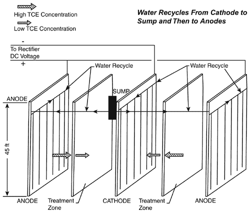
The Lasagna technology typically employs electrode zones, multiple treatment zones, and a water management system. At SWMU 91, construction of the treatment system began with the installation of electrode zones (Figure 1), which consisted of three 72-ft rows of electrode assemblies placed at a depth and spacing of 45 feet. Each assembly contained a 9-in by 40-ft carbon steel plate and a 4-in by 45-ft wick drain wrapped inside a geotextile material. Construction of the treatment zones involved offsite mixing of a 60:40 (by weight) slurry of cast iron particles and kaolin. A cement truck transported the slurry to the site, where it was placed below the ground surface to create two treatment zone sections consisting of eight parallel 45-ft-deep curtains spaced at 5-ft intervals. The water handling system consisted of PVC piping, a collection sump, and a 400-gal storage tank located in the center of the treatment area.

Induced water flow (electro-osmosis) was generated across the treatment zones using direct current. The electrical field (initially set at 450 volts and 800 amps and then converted to 220 volts and 600 amps three months later) caused the pore water to move uniformly from the anode toward the cathode through the treatment zones. The pore water moved more than 10 feet during the entire operational period, forcing contaminants through at least two treatment zones. Iron filings in the treatment slurry degraded the TCE to ethane (a nontoxic gas) and chloride (a natural component of ground water), and will remain in the ground to "polish" the soil over time.
The system operated on a continuous mode for approximately six months, at which time the soil temperature reached 90°C. It then was converted to a pulse mode to prevent overheating. Pulsed operations allowed the system to operate for 1-4 days until the target temperature was reached, and then to shut down for several days of cooling before re-starting. Sampling conducted one year after operations began showed that TCE concentrations had declined from an average pre-treatment concentration of 43.3 mg/kg to less than 1.5 mg/kg, and that the highest concentration had decreased from 552 mg/kg to 27 mg/kg. Operations continued for eight additional months.
Site inspections were conducted weekly. The system ceased operation temporarily for approximately eight weeks after 20 months of operation due to problems with the rectifier converting incoming alternating current into direct current. Minor problems arising during operations involved:
- unscheduled power outages;
- installation of an above-ground water reservoir tank in response to heavy rain;
- removal of sediment from a water recycling line;
- installation of a vent hose to prevent false high sump readings caused by trapped air; and
- spikes in the sump level sensor due to electrical interference.
System operations were terminated in December 2001 after a total of 24 months, without the need for an additional one-year option outlined in the project plans. Data indicated the target cleanup level for TCE (5.6 mg/kg) had been met. Sampling and analysis conducted in Spring 2002 confirmed that TCE concentrations had further decreased, resulting in an average of 0.38 mg/kg and a high of 4.5 mg/kg. A total of approximately 10,000 yd3 of soil were treated at a unit cost of $200/yd3.
The final remedial action report for this project is available from the RTDF at http://www.rtdf.org/public/lasagna/lastechp.htm. Planning of additional Lasagna applications is underway, including use by the State of Wisconsin for redevelopment of a half-acre brownfields site at an estimated unit cost of $110/yd3.
Contributed by Gary Bodenstein, DOE/Paducah Site (270-441-6831 or bodensteingw@oro.doe.gov) and Chris Athmer, Terran Corporation (937-320-3601 or cjathmer@terrancorp.com)
Large-Scale Bioslurping Operations Used for Fuel Recovery
Since 1996, the U.S. Air Force has been using bioslurping to recover JP-5 fuel from unsaturated soil at a facility on the island of Diego Garcia, in the Indian Ocean. Based on bioslurping’s initial success and subsequent technology developments, the Air Force Center for Environmental Excellence (AFCEE) expanded and enhanced the system over the past few years to encompass three treatment areas. To date, more than 100,000 gallons of fuel have been recovered by the bioslurping system. Bioslurping augmented by natural bioventing has facilitated the aerobic microbial degradation of an estimated 250,000 pounds of fuel in the subsurface.
The subsurface along the coast of Diego Garcia is characterized as a mixture of sand and crushed coral rock. A fresh-water lens about four feet below ground surface floats on top of denser saltwater. As a result of tidal action, the water table varies approximately two feet, exposing the contaminant zone to aeration. These conditions provide an optimal setting for bioslurping technology, which relies on the replenishment of oxygen for aerobic biodegradation. The oily smear zone created above the water table as it rises and falls reduces the amount of floating fuel and increases the exposure of subsurface fuel to aerobic biodegradation.
As a form of vacuum-enhanced skimming to collect fuel floating on a water table, a typical bioslurping system consists of a vacuum pump connected by pipes to standard fuel recovery wells. A dip tube is placed inside a sealed well, with the straw inlet placed in the water/floating fuel. The top of the dip tube connects to pipes that carry the fuel and soil gas drawn in by the vacuum pump. Soil gas enters the well through a screened interval above the water table. From the vacuum pump, the fuel/water mixture is piped to a separator where the fuel is removed and collected for recycling. Vapors are discharged directly to the atmosphere or treated, if needed, and discharged. The bioslurping system pulls oxygen-rich air from the atmosphere into the unsaturated soils, thus bioventing the unsaturated soil and fostering aerobic microbial degradation of the contaminants.
The first bioslurper at Diego Garcia was installed in a grassy area near an airstrip. It included a vacuum pump and 1,100 feet of 4-inch PVC piping connected to six downgradient recovery wells. Dip tubes were placed approximately one foot into the water/fuel during low tide. A 10-horsepower vacuum pump operated 24 hours per day to generate a vapor flow rate averaging 50 ft3/min. During the first month of operation, 2,000 gallons of fuel were recovered. Recovery rates over the following 18 months averaged approximately 1,000 gallons of fuel per month. Recovered fuel was used to power water heaters for other onsite operations.
In 1997, a second bioslurper was added in a nearby aircraft ramp area. The bioslurper employed an identical vacuum pump that was connected through manifolds to the original vacuum pump. Piping was installed among ten additional recovery wells and the vacuum pump, and connected to the existing pipe system. Hose clamps and elastic couplers were used for pipe connections to allow for rapid disassembly in the event of contingency military activities. During the first month of operation, 8,000 gallons of fuel were recovered from the combined bioslurping systems. The recovery rate averaged 5,000 gallons per month over the following year, when contingency aircraft operations took effect. During this event, the bioslurper piping was removed and the ramp was ready for aircraft operations within four hours.
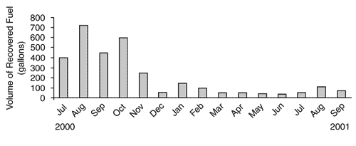
In 2000, the bioslurping system was further expanded to remediate all areas of the site known to contain fuel product in the subsurface. The expanded system involves a total of 50 bioslurper wells, some of which are used only as biovents in areas that do not contain floating fuel product. Within two to three years of operation, the thickness of the product decreased significantly in most wells. Between September 1998 and December 2000, for example, the average product thickness in 10 wells in the aircraft ramp area decreased 100%, from an initial thickness of 1.26 feet. Similarly, the volume of subsurface fuel at a refueling pit within the ramp area decreased more than 80% between July 2000 and September 2001 (Figure 2).

While 25 recovery wells each contained more than one foot of fuel accumulation prior to treatment, only eight wells in the ramp area had fuel accumulations exceeding one foot in May 2002. None of the wells near the airstrip contained any detectable fuel accumulation. Overall, the rate of contaminant degradation for this system is estimated at 1 pound of hydrocarbon per 13 pounds of air introduced into the soil.
The Air Force continues to conduct quarterly sampling in the recovery wells and semi-annual sampling of ground water to monitor dissolved fuel contaminant concentrations and indicators of natural attenuation. In addition, soil gas is field tested at selected locations to track the degradation of contamination in the smear zone above the water table. The bioslurper will continue to operate until fuel recovery becomes nonproductive, at which time operations will convert to a bioventing mode until soil gas tests indicate that aerobic degradation is complete. Natural attenuation processes, including tidal-mediated bioventing, are expected to degrade the residual fuel in the soil and the small quantities of fuel constituents dissolved in the ground water.
AFCEE estimates that bioslurping will remove the remaining recoverable fuel, which exists at only one of the three treatment areas, by the end of 2003. AFCEE also estimates that the technology will cost approximately 5% of the amount required to excavate and replace the entire site with clean fill-the alternative cleanup remedy.
AFCEE recently assembled a mobile diesel-powered bioslurping system that can be used on an operational ramp while connected to 6-10 wells. The system allows fuel recovery from wells to continue without disruption to air operations. In field tests conducted at the site earlier this year, the mobile bioslurper recovered 260 gallons of fuel within four months.
Contributed by Jerry Hansen, AFCEE (210-536-4353 or jerry.hansen@brooks.af.mil) and Donald Kampbell, Ph.D., U.S. EPA/Office of Research and Development (580-436-8564 or kampbell.donald@epa.gov)
Propane Biostimulation Barrier Demonstrated in MTBE-Contaminated Ground Water
The U.S. EPA’s National Risk Management Research Laboratory (NRMRL) and U.S. Navy recently completed a technology demonstration at the Naval Base Ventura County (NBVC) in Port Hueneme, CA. The demonstration was undertaken to determine whether biodegradation is reducing intrinsic methyl tertiary butyl ether (MTBE) in ground water to concentrations below state criteria. Fifteen ground-water sampling events were conducted over a 38-week period. Analysis of intrinsic MTBE, deuterated MTBE (d-MTBE), daughter products, and geochemical parameters demonstrated that the technology did not meet the State of California’s treatability criteria (below 5µg/L).
From June 2001 to March 2002, the demonstration was conducted at the NBVC National Environmental Technology Test Site, where approximately 10,800 gallons of fuel had been released into ground water from 1984 to 1985. The resulting ground-water plume consists of approximately 9 acres of BTEX and 36 additional acres of MTBE contamination. The plume extends approximately 4,500 feet downgradient from the release site. Pre-treatment data indicated that MTBE concentrations in the demonstration area, located midway downgradient along the MTBE plume, reached 5,000 µg/L.
The site is underlain by unconsolidated sediment composed of sands, silts, clays, and minor amounts of gravel and fill. A shallow, perched, unconfined aquifer is the uppermost water-bearing unit. The aquifer consists of an upper 8- to 10-ft silty sand unit and an underlying 12- to 15-ft fine- to coarse-grained sand unit, underlain by a basal clay layer. The water table is located 6-8 feet below ground surface, with a saturated aquifer thickness of 16-18 feet (reflecting 1-2 feet of seasonal variation). Pre-demonstration study showed little ground-water flow other than in the bottom portion of the aquifer.
The demonstration tested the ability of a propane biostimulation barrier to stimulate cometabolism through the injection of oxygen, propane, and MTBE-degrading bacteria into the aquifer. Exogenous propane-oxidizing bacteria (Rodococcus ruber strain ENV425) were used to seed the aquifer at the demonstration onset. Oxygen and propane then were sparged intermittently into the aquifer from separate sparging points at a rate of 1-10 pounds/day and 0.1-0.5 pounds/day, respectively.
Operations in the test plot began with the injection of oxygen into eight oxygen injection points (OIPTs) and propane into seven propane injection points (PIPTs). Eight bacterial injection points installed between the OIPTs and PIPTs were used for a single release of bacterial suspensions 16 days after the start of oxygen injection. Only oxygen was injected at eight OIPTs in the control plot. The ground-water injection and tracer systems for the two plots together employed a total of 38 fully-screened wells.
Deuterated MTBE and ground-water tracers (bromide and iodide) were used to determine the technology’s efficacy. Tracers were released into each well under the natural gradient at a rate of 10 mL/day. The ratio of tracers between downgradient transects provided evidence of MTBE dilution and degradation, while d-MTBE ratios served as tracers of anthropogenic MTBE. Critical evidence of biodegradation was provided by measurement of d-MTBE daughter products.
The first ten sampling events took place biweekly in both the test and control plots and monthly thereafter. Although sampling was concentrated at the bottom well screens, the middle and upper screens of each well were sampled periodically. Both the test and control plots contained very low levels of daughter products (acetone; acetone-d6, 2-propanol; 2-propanol-d6,d8; formaldehyde; tertiary butyl alcohol (TBA); and tertiary butyl alcohol-d9,d10). While only TBA was detected at upgradient wells, both TBA and d-TBA were detected in downgradient wells; a determination of whether biotic or abiotic processes generated these products was not made. The d-MTBE in both the test and control plots increased throughout the evaluation period.
Geochemical parameters in the upgradient and downgradient portions of both the control and test plots were analyzed after the evaluation period. Analysis showed no reduction in nutrients or in total and dissolved organic carbon (electron donors) in either plot, and no alkalinity change in the downgradient portion of the test plot. These results suggested little biodegradation was occurring.
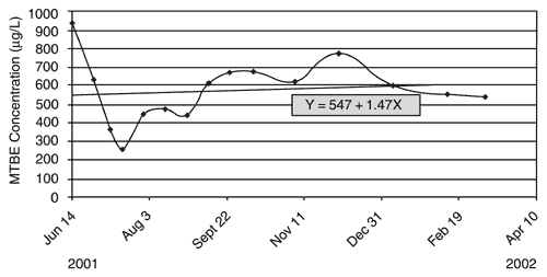
Throughout the 38 weeks of testing, intrinsic MTBE concentrations in the upgradient portion of the test plot and in both upgradient and downgradient portions of the control plot gradually decreased. MTBE concentrations in the downgradient portion of the test plot, however, remained at 300-600 µg/L throughout testing (Figure 3). More information on this evaluation is available in NRMRL’s innovative technology evaluation report (EPA/600/R-02/092) at http://www.epa.gov/ORD/NRMRL/Pubs).

Contributed by Ann Azadpour-Keeley, EPA/NRMRL (580-436-8890 or keeley.ann@epa.gov)
Phyto Demonstration Enters 7th Year at Carswell Naval Air Station
An extensive interagency demonstration of phytoremediation was initiated in 1996 at the Carswell Naval Air Station RCRA site in Fort Worth, TX. The system uses eastern cottonwood trees, Populus deltoides, as short-rotation woody crops to optimize in-situ reductive dechlorination of trichloroethene (TCE) and cis-1,2-dichloroethene in shallow ground water. Results after three years of monitoring indicated that the planted trees had rooted into the water table and begun to exhibit hydraulic and geochemical influences at the site.
Earlier this year, the U.S. Geological Survey (USGS) and U.S. Air Force (USAF) conducted a six-year review of the system and found that the trees have significantly increased biodegradation rates of TCE beneath the center line of the plantations. Associated with this increase in biodegradation, or natural attenuation capacity, is a substantial decrease in plume stabilization distance (the extent to which contaminants travel in the upper aquifer). USGS modeling results suggest that solvent-based contaminant mass flux decreases due to in-situ microbial biodegradation will be significantly larger than decreases due to transpiration. A 20% decrease in mass flux from transpiration alone during the peak of each growing season is anticipated when canopy closure is achieved.
The treatment area is located about one mile from the main aircraft assembly building at USAF Plant 4, where waste oil, solvents, and fuels had been disposed at an onsite landfill. Previous use of a pump and treat system and steam-enhanced vacuum extraction addressed only some of the site’s solvent-based source contamination. The area encompasses 4.6 acres that were covered primarily with grass prior to treatment. Surface soil consists of a 12- to 18-in layer of silty clay and clayey silt. Ground water is located 5-15 feet below ground surface, with an estimated velocity of 0.62 ft/day. The underlying shallow aquifer consists of silty fine sands and hydraulically isolated lenses of coarser material, with an estimated conductivity of 10-2 cm/sec. Prior to treatment, TCE concentrations in the ground water approached 1,000 ppb.
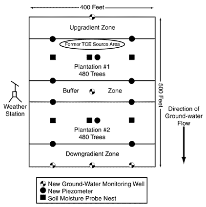
Approximately 960 trees were planted evenly in two 60- by 250-ft plots positioned perpendicular to the direction of ground-water flow. The plots are separated by a 50-ft buffer zone (Figure 4). One plot is located directly above a former waste trench, while the second is located downgradient of the trench. Each plot consists of seven rows of trees planted 4-8 feet apart. A drip irrigation system was installed and used on a regular basis during 1996, the first year of tree growth, to help establish them during a severe drought. The irrigation system was used once during 1997; since then, the trees’ facultative phreato-phytes have used both ground water and precipitation. Plant tissue analysis has indicated that eventual disposal of the trees as hazardous waste will be unnecessary.

Hydrologic and geochemical data collected from 40 monitoring wells in August 1996 through September 1998 showed that dissolved oxygen levels beneath the trees had decreased. This suggested that the trees are providing a sustained source of the electron donors needed for reductive chlorination. Data indicate that a combination of hydraulic control and in-situ microbially mediated reductive dechlorination is responsible for the mass flux reduction.
The USAF anticipates follow-up data collection through 2006, which will mark the tenth year of tree growth. The estimated full-scale cost for this application is $466,000. EPA’s National Risk Management Research Laboratory is compiling detailed cost information on this project in an innovative technology evaluation report, which will be available at www.epa.gov/ord. In addition, DOD will issue a final cost and performance report later this year. If warranted by the final results of this application, the USAF anticipates the use of phytoremediation for other ground-water contaminants such as nitrates and metals.
Contributed by Gregory Harvey, USAF (937-255-3276 or gregory.harvey@wpafb.af.mil)


