
- Featured Articles
- Site Operations and Remedy Design: Hurricane Irene Flooding and Adaptation at the American Cyanamid Site
- Remedy Performance: Remedy Resilience to Flooding at the Rocky Mountain Arsenal
- Remedy Design: Long-Term Protective Measures Against Storms and Flooding at Allen Harbor Landfill
- Resources
 Download This Issue in Adobe PDF® Format
(811KB/9pp/PDF)
This issue of Technology News & Trends highlights how remedies for contaminated sites may be vulnerable to the impacts of climate change and how measures may be taken to adapt remedies to the impacts. Potential impacts include extreme or sustained changes in temperatures, increased flood events or droughts, increased wind intensity, more frequent and intense wildfires, and sea level rise. The U.S. Environmental Agency (EPA) Superfund program has developed an approach that raises awareness of the vulnerabilities and applies climate change science as a standard business practice in site cleanup projects. Articles featured in this issue examine vulnerabilities at three National Priorities List sites, describe the effects of intense weather events at these sites, and detail adaptation measures already implemented or planned to increase the remedies' resilience to climate change impacts.


Site Operations and Remedy Design: Hurricane Irene Flooding and Adaptation at the American Cyanamid Site
Contributed by Joe Battipaglia, U.S. Environmental Protection Agency, Region 2
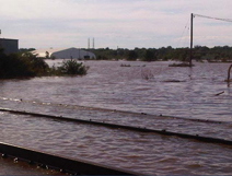
Figure 1. Inundation of the north area of the American Cyanamid site with five feet of standing water after the floodwaters receded; during the hurricane, the Raritan River from its typical elevation of approximately 18 feet above mean sea level to an elevation of 42 feet.
Hurricane Irene struck the coast of New Jersey in late August 2011. On August 27, associated floodwaters overtopped a 100-year flood control berm that surrounds much of the American Cyanamid site, a 435-acre National Priorities List site located along the Raritan River in central New Jersey's Somerset County. Approximately 214 million gallons of standing water remained in the site's north area as floodwaters receded (Figure 1). Due to the potential for major storm events to occur in the future, extensive flood plans were developed approximately six months later to integrate preparedness procedures, evacuation plans and post-flood response requirements into site operations. A number of adaptation measures were implemented throughout the site to increase its flooding resilience and improve flood response efforts. Flood mitigation measures were also integrated into the preliminary design of a remedy selected in 2012, which addresses six impoundments, site-wide soil and groundwater.
The site contains 27 impoundments, 21 of which were used to dispose of chemical sludge and other wastes. Onsite soil and groundwater are contaminated with volatile organic compounds (VOCs), semi-VOCs and metals; the main contaminants of concern are benzene, 1,2-dichlorobenzene, n-nitrosodiphenylamine, nitrobenzene and naphthalene. The two most contaminated impoundments (1 and 2) each contain waste 13 to 16 feet deep and cover approximately two acres. To maintain hydraulic control of groundwater in the north area, a minimum of 650,000 gallons of groundwater per day has been extracted and discharged to a nearby sewage treatment plant since 1988.
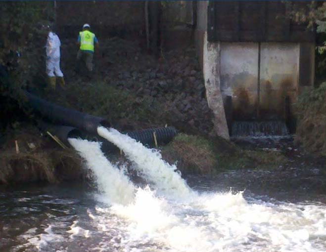
Figure 2. Controlled release of floodwater into Cuckel's Brook at a rate averaging 5,200 gallons per minute, at a location close to the former sluice gate discharge point.
Floodwaters entering the site were prevented from exiting due to an inoperative mechanical sluice gate, which created a "bathtub" within the 10- to 12-foot flood control berm of the 268-acre north area. After analyzing samples of the standing floodwater, it was determined that the controlled release of the floodwater into the adjacent Cuckel's Brook would not negatively impact its water quality. By September 28, approximately 152 million gallons of floodwater had been discharged to the brook (Figure 2) using generator-powered pumps on a swamp buggy. Throughout the controlled discharge, Cuckel's Brook and the connecting Raritan River were monitored to ensure downstream water quality and communities were not adversely affected. The remaining 62 million gallons of standing water was primarily captured by the site's stormwater management system, with lesser volumes evaporating or infiltrating to groundwater.
The potential for a surficial release or catastrophic failure of the berms surrounding impoundments 1 and 2 was a concern during the flood (Figure 3). These impoundments are located in the site's south area, approximately 700 feet from the river and outside of the site's flood control berm. Unreinforced earthen berms were constructed around the two adjacent impoundments in the mid 1900s to contain waste and control floodwaters. Before the floodwaters receded, surface water samples were collected from standing water in the vicinity of the impoundments and from downstream points of the Raritan River. Results from the post-flood surface water sampling and berm inspections indicated that a significant release did not occur.
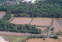
Figure 3. Area comprising impoundments 1 and 2 that remained flooded two days after the peak of Hurricane Irene flooding.
Due to the elevated floodwater levels and loss of electrical power, the site's groundwater extraction system was shut down for approximately 30 days. Post-flood modeling estimated a contaminant travel distance of approximately 160 feet during the 30-day shutdown, with ultimate recapture after the system was restarted.
Based on an updated flood hazard map for the site (Figure 4), EPA approved a flood emergency preparedness plan (FEPP) in March 2012 that provides control measures and procedures to protect the site, personnel and equipment. The FEPP includes guidelines for issuing flood alerts, warnings and emergencies as well as security procedures, evacuation plans and procedures. Soon thereafter EPA approved a flood management and response plan (FMRP) that identifies facility operational management and response procedures required for flooding. The FMRP includes inspection and maintenance procedures for flood preparedness, pre-flood preparations and post-flood conditions such as site entry, recovery and restoration.
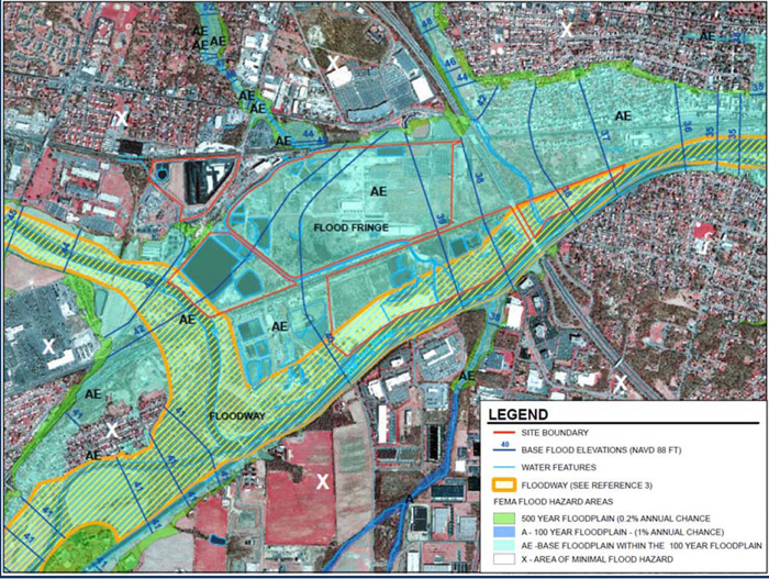
Figure 4. Flood hazard map illustrating the American Cyanamid site's location within both the 100-year and 500-year floodplains, with southeastern portions of the site lying within the Raritan River floodway.
Implementation of the FEPP and FMRP, which have been updated several times to account for changing project aspects and site conditions, has been integral to the site's recovery and to measures being taken to address flood-related vulnerabilities. Following Hurricane Irene, a new drum storage area was built so that containerized wastes could be stored outside of the flood hazard area. In the north area, the sluice gate was repaired to enable rapid site drainage and a 360-foot damaged portion of the flood control berm was restored; the associated spillway was reinforced with concrete-grouted riprap. Also, onsite security and staff trailers were relocated to a non-contiguous portion of the site located outside the flood hazard area, and a contract was secured for accelerated access to an outboard motor-equipped boat to aid future flood emergency/recovery efforts. To assure electrical power is retained during future storms, critical onsite electrical infrastructure was raised to elevations 5 feet higher than Hurricane Irene flood levels.
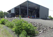
Figure 5. Elevated groundwater treatment plant constructed as part of an EPA removal action; the treatment process includes metals precipitation, filtration and carbon adsorption.
The site's groundwater extraction system has also been adapted for the increased frequency of major flood events. Both of the existing turbine pumps used to extract groundwater for offsite treatment were replaced with submersible pumps designed to allow for uninterrupted pumping during future floods. In April 2012, an interim onsite groundwater treatment system was constructed to treat groundwater captured by a collection trench intercepting discharges to the Raritan River. The treatment system was constructed at an elevation more than 1 foot higher than the flood levels experienced during Hurricane Irene (Figure 5).
Adaptation measures implemented to reduce the vulnerabilities of impoundments 1 and 2 included installing new HDPE covers on the impoundments to reduce the potential for waste mobilization during floods, as well as reinforcing the berms to increase their strength and prevent flood-related scouring. A high-strength, ultraviolet-stabilized, multi-layered synthetic matting with a fiber matrix material (commonly known as a turf reinforcement mat [TRM]) was installed on the berm banks to serve as a soft armor for erosion control and vegetation stability (Figure 6). The TRM is designed to withstand water velocities in excess of 8 feet per second.
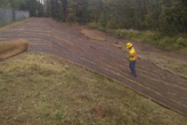
Figure 6. TRM strips approximately 6.5 feet wide deployed vertically along the outer portion of the berms surrounding impoundments 1 and 2 and anchored with metal pins prior to revegetation.
Recent selection of a remedy also reflects adaptations to account for potentially increased frequency of major flood events. In September 2012, the remedy for operable unit (OU)4 was selected to address six impoundments, site-wide soil and groundwater. The remedy is currently in the design phase and involves in situ solidification/stabilization followed by construction of an impermeable multi-layered cap on over 60 acres and a 2-foot soil cap on more than 130 acres. The record of decision requires all engineered caps to be designed and constructed to withstand effects of a 500-year flood event, at a minimum. In addition to withstanding direct effects of flooding, the OU4 engineered caps are required to be designed and constructed to ensure resilience to indirect climate/weather hazards posing potential threats, such as inadequate drainage, slope instability, erosion, freeze/thaw cycle effects and altered surface vegetation.
A major goal of the OU4 remedial design is to minimize loss of the site's floodwater storage capacity so that flooding of downstream communities is not exacerbated. Potential measures include constructing a natural stormwater management system and removing the site's flood control berm, which would increase the flood storage capacity by over 200 million gallons during more common flood events. The OU4 remedial design as well as general site operations were not modified due to experiences associated with the more recent Hurricane Sandy along the New Jersey coast, which generated less than three inches of precipitation at this site.
Remedy Performance: Remedy Resilience to Flooding at the Rocky Mountain Arsenal
Contributed by Greg Hargreaves, U.S. Environmental Protection Agency, Region 8
The effects of heavy rainfall and associated flooding in and around Denver, Colorado, in September 2013 prompted close monitoring and frequent inspection of containment and treatment remedies at the Rocky Mountain Arsenal. Since the 1970s, cleanup of this National Priorities List site has involved 31 projects addressing approximately 3,000 acres of soil, 15 groundwater plumes and nearly 800 structures. Flood-related vulnerabilities of highest concern focused on two capped hazardous waste landfills covering 84 acres and approximately 450 additional acres containing six RCRA-equivalent evapotranspiration covers.
The former arsenal encompassed 17,000 acres (27 square miles) used by the U.S. Army to manufacture chemical warfare agents and incendiary munitions during World War II. From 1946 through the 1980s, portions of the arsenal were leased to companies manufacturing industrial and agricultural chemicals. Various waste products were stored, handled or disposed on the site, and solid waste was disposed in onsite burn pits, sanitary landfills, basins and trenches. As a result, over 600 potential contaminants were identified in soil and/or groundwater, with highest contamination relating to organochlorine pesticides, heavy metals, agent-degradation products and manufacturing byproducts, as well as chlorinated and aromatic solvents. The U.S. Army and Shell Oil Company maintain the capped landfills and RCRA-equivalent covers, which blend with the surrounding short-grass prairie land designated as the Rocky Mountain Arsenal National Wildlife Refuge. The 15,000-acre refuge, which is managed by the U.S. Fish and Wildlife Service (USFWS), includes areas where cleanup activities were completed.
Soil remediation design focused on interrupting the contaminant exposure pathways by: (1) placing the most contaminated soil (and structure demolition debris) in two onsite RCRA Subtitle C landfills, and (2) consolidating less contaminated soil and structure debris where excavation was infeasible and constructing six RCRA-equivalent covers. Each landfill base includes two 3-foot compacted clay layers with composite liners, leachate collection systems, and composite leak detection and collection systems. Due to higher toxicity of waste in one landfill, its base liner includes a third 3-foot compacted clay layer and geosynthetic liner system, as well as a second leak detection/collection system. The final caps include: (1) a bottom layer of crushed concrete to prevent biointrusion and promote gas venting, (2) geosynthetic membranes, (3) a 4-foot-thick rock-amended soil layer, (4) a diverse mix of vegetation, and (5) a system of drainage channels constructed of articulated concrete block.
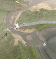
Figure 1. Overflow of the arsenal's network of stormwater holding ponds due to record-breaking rainfall and subsequent rupture of the Havana Ponds dam.
The six RCRA-equivalent covers use evapotranspiration technology with a capillary barrier, rather than geosynthetic materials. This design aims to allow zero percolation into underlying waste, prevent biointrusion, control erosion by wind and water, and minimize ponding. Each cover consists of four layers containing (from bottom to top): (1) 16 to 18 inches of crushed concrete serving as a biota barrier, (2) 1 to 3 inches of pea gravel (or in one case nonwoven geotextile) to create a capillary barrier, (3) 48 inches of soil, and (4) a diverse mix of vegetation. Each cover system includes a network of drainage channels constructed of concrete and grass-lined swales.
Construction of the caps and covers was completed in 2010. Between September 9 and 16, 2013, more than 15 inches of rain fell in the Rocky Mountain front range, which is equivalent to the area's average precipitation in one year. Gauges at the arsenal measured more than 8.2 inches of rain, with 3 inches falling on September 12 alone. The National Oceanic and Atmospheric Administration considers the precipitation a 500- to 1,000-year storm event.
On September 12, stormwater surging onto the arsenal caused a breach of the downgradient Denver-owned Havana Ponds dam inside the wildlife refuge (Figure 1). Associated currents carved an 8-foot-deep gully through the refuge and washed out roads, trails and other local infrastructure. More than 400 acres of the refuge were submerged during peak flooding, and billions of gallons of water from the South Platte River watershed (including the arsenal) flooded surrounding areas. The U.S. Army pumped out water that accumulated behind a former railroad embankment nearby, and the USFWS opened valves to relieve pressure on stormwater holding ponds within the refuge.
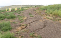
Figure 2. Erosion at the capped landfills, primarily on access roads.
Overall, the arsenal suffered more than $20 million in damage caused by the flooding. Post-storm assessments indicated that the two capped landfills were relatively resilient to the flood; both were designed to withstand a 1,000-year, 24-hour storm event. During the flood, sheet flow from the rock-amended soil on the RCRA-Subtitle C landfill caps drained to the concrete block channels as anticipated, with minimal development of erosion rills (Figure 2) and only minor sediment accumulation at the channel ends (Figure 3). Additional sediment accumulated in leachate-riser control buildings above one landfill but caused no damage to the instrumentation, pumps or auxiliary systems. Small graders were used to remove the accumulated sediment within one week of floodwater peak.
The RCRA-equivalent covers also performed effectively during the flood. Their low slopes helped minimize formation of rills or gullies, and sheet flow effectively drained to the concrete channels that directed stormwater to surrounding drainage basins. These channels had been designed to withstand a 100-year 24-hour storm event. Associated sediment accumulated primarily outside the cover perimeter, at low points on an access road with additional drainage channels.
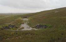
Figure 3. Stormwater runoff carrying loose sediment, which settled within downgradient ends of the concrete block drainage channels.
Other onsite remedies also were monitored during the flood and inspected after floodwaters receded. Although operation of the site's five groundwater treatment facilities ceased during electricity outages at the time of flooding, the facilities suffered no physical damage due to their positions at elevations higher than peak floodwater. Power outages similarly affected operation of skimming pumps and other equipment used to recover dense non aqueous-phase liquid (DNAPL) recovery. Due to changing hydraulic conditions, the DNAPL transfer pumps began operating outside their design parameters as floodwaters continued to rise. Future groundwater monitoring is anticipated to reveal if the site's subsurface slurry walls remain intact and whether groundwater capture/controls were adversely affected by the flood. Visual inspections indicated no damage to the site's fencing and signage.
Long-term monitoring of the capped landfills, RCRA-equivalent covers and groundwater containment/treatment systems will consider potential increases in frequency or intensity of future flood events, as well as potential droughts and related indirect impacts, such as altered rates of evapotranspiration. Several components of the cover designs are expected to maintain their long-term performance and resilience to climate change. For example, their biointrusion layers consist of highly durable material (recycled concrete from former Stapleton Airport runways) with a minimum compressive strength of 2,000 pounds per square inch, weight exceeding 130 pounds per cubic foot, and resistance to moisture-induced degradation.
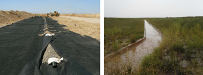
Figure 4. Broken-back design and low-slope drainage provided by 6-inch-diameter slotted pipe secured beneath 4 feet of soil overlain by concrete channeling; the September stormwater drained effectively through the channels, despite heavy saturation of surrounding soil.
Also, erosion controls for the RCRA-equivalent covers were designed to limit overland flow lengths to 500 feet, which minimizes rill and gully formation. Their designs reflect an overall slope of 3 percent in a "broken back" configuration involving drainage channels cut through the covers (Figure 4). A total of 2.5 miles of drainage channels, ranging from 150 to 2,246 feet in length, were installed at grades of 0.3 to 1 percent across the 450 acres. The covers' ability to withstand extreme wind and precipitation and related erosion is reinforced by their ground surface vegetation. It comprises a diverse mixture of shallow- and deep-rooted native plants intended to maximize water removal and increase resilience to indirect effects of a changing climate; effects could involve pathogen and pest outbreaks or land surface disturbances such as wildfires and wildlife overgrazing.
The landfills' leachate collection systems and leak detection/collection systems are monitored monthly. Monitoring of the RCRA-equivalent covers includes monthly collection of lysimeter data indicating percolation rates, annual quantitative inspections of the vegetation, and visual inspections at least seven times each year for erosion, burrowing animals and overall integrity. Total soil loss and/or settlement of each cover is monitored through use of erosion monuments to help identify needed repairs relating to rills, gullies, excessive sheet erosion, settlement and apparent ponding. In addition, data from a network of water-content reflectometers placed within the soil profile of one cover are collected continuously and analyzed quarterly to monitor moisture content and migration at 6-inch intervals throughout the 4-foot-thick soil layer.
Overall, the remedies performed as designed and their integrity was not compromised during this 500- to 1,000-year storm event. Future monitoring will include considering the need for vegetation replacement in any areas suffering from an altered climate. Additionally, the USFWS intends to prepare a comprehensive conservation plan and an environmental impact statement for the refuge, which may include wildlife and habitat management practices in light of possible climate change and declining precipitation.
Remedy Design: Long-Term Protective Measures Against Storms and Flooding at Allen Harbor Landfill
Contributed by Christine Williams, U.S. Environmental Protection Agency Region 1
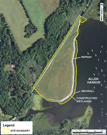
Figure 1. Allen Harbor Landfill boundary and its proximity to Allen Harbor. Riprap protects the landfill face.
The U.S. Navy, working with EPA and other federal and state partners, integrated shoreline armoring structures, including a line of riprap, wetlands and a seawall into the remedial design of a coastal landfill at the former Davisville Naval Construction Battalion Center (NCBC) Superfund site. The structures are designed to protect the landfill face from erosion through wave action, tidal forces and storm surges in the adjacent Allen Harbor. The harbor is located on the western shore of Narragansett Bay, Rhode Island, and surrounds the landfill on three sides (Figure 1). A 3-foot deep multimedia cap installed concurrently reduces the potential for leachate generation from precipitation, while its placement at the 100-year flood elevation level ensures its continued integrity during smaller, more frequent storm and flooding events. The storm mitigation measures are expected to provide long-term protection for human and ecological exposure to landfill contaminants with minimal contaminant migration into Allen Harbor.
The 15-acre Allen Harbor Landfill was used for the disposal of waste by NCBC Davisville and the Naval Air Station Quonset Point from 1946 to 1972. Materials disposed of at the landfill included municipal-type waste, construction debris, rubble, preservatives, paint thinners, solvents, polychlorinated biphenyls (PCBs) from transformers, fuel oil, asbestos, ash, sewage sludge and waste fuel oil. The landfill was closed in 1972 with the placement of a discontinuous 2-foot-thick soil cover over the landfill materials.
An investigation by the Department of Defense in 1984-1985 under its Installation Restoration Program indicated that surface water, sediment and shellfish samples collected from Allen Harbor were contaminated with volatile organic compounds (VOCs), PCBs and metals. The Navy completed the remedial investigation (RI) in 1996. Groundwater and soil samples from the landfill area, as well as sediment samples from Allen Harbor collected during the RI, indicated elevated concentrations of VOCs and semi-VOCs, polycyclic aromatic hydrocarbons (PAHs), pesticides, PCBs and metals.
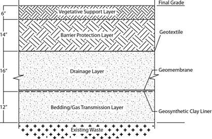
Figure 2. Multimedia cap layer composition: bedding and gas transmission layer covered with a geosynthetic clay liner and geomembrane, a drainage layer covered with a geotextile, a barrier protection layer, and a soil layer to support vegetation growth.
The potential for leachate generation, erosion of the landfill face, contaminant transport from the erosion and overland runoff to intertidal sediment were the primary concerns considered in selecting the remedy. A multimedia cap was chosen for its capacity to reduce runoff and erosion, decrease the potential for infiltration of precipitation, and prevent human and animal contact with contaminants in site surface soil. The cap is composed of several layers (Figure 2): a 12-inch bedding and gas transmission layer directly above the waste; a Bentomat® geosynthetic clay liner, which consists of two layers of geotextiles surrounding low-permeability sodium bentonite and needle-punched together to increase internal shear resistance; a textured 40-mil VFPE (very flexible polyethylene) geomembrane liner; a 16-inch drainage layer; a 14-inch barrier protection layer above a geotextile barrier; and a 6-inch vegetative support layer.
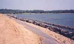
Figure 3. Soil cap at Allen Harbor Landfill soon after completion and prior to planting vegetation.
The multimedia cap was constructed in areas above the 100-year flood elevation, at 14 feet above mean sea level (MSL) and higher, to avoid compromising the long-term effectiveness of the cap from hydrostatic pressure on the liners during floods. The remainder of the landfill is covered with a soil cap (Figure 3). To construct the soil cap, the original soil cover installed in 1972 was regraded, and an additional 18-inch common borrow fill layer was emplaced along with a 6-inch layer to support vegetation. Sediment dredged from the entrance to Allen Harbor was used as grading material whenever possible.
The multimedia cap and soil cap were graded at least 3 percent to promote precipitation runoff, and were seeded and vegetated (Figure 4). The site team determined that precipitation would run off the slope and into the swales, which focus the runoff into the harbor. In addition, while groundwater flow and the subsequent discharge of groundwater from the landfill is to Allen Harbor, the actual pathway that contamination follows is physically and temporally longer than previously understood, and continued migration of contamination from the landfill to the nearshore has not been observed, based on monitoring.
Figure 4. Vegetation cover and monitoring wells on Allen Harbor Landfill.
The remedy also included placement of riprap along the entire shoreline of the landfill to stabilize and protect the landfill from erosion during tidal rise and storm surges. Riprap on the eastern shore consists of 3,000-pound, 6-foot thick armor stones from about 15 feet above MSL to sea level, while stones at the same level on the northern and southern shores have a 1- to 2-foot average diameter. Smaller stones of an average of 3- to 6-inch diameter were emplaced from sea level to about 15 feet below MSL. A layer of small, 1-inch minimum size filter/bedding stone underlies the riprap.
About 1.5 acres of intertidal wetlands on the eastern shore of the landfill were restored by federal and state partners just before cap construction was complete (Figure 5). The work consisted of removing all common reeds (Phragmites australis) from the existing impacted wetlands, replacing the adjacent polluted mudflat with a layer of rocks topped by dredge spoils (from the harbor entrance channel), and planting deep-rooted cordgrass (Spartina) on the modified surface. A seawall embedded up to 15 feet below MSL and rising to a few feet above MSL separates the wetland from the harbor where the potential for storm surge is highest. The constructed wetland and seawall act together to trip waves and reduce energy reaching the riprap.
Figure 5. Wetland under construction in front of the landfill cap.
All remedial work was completed in 1999, and long-term monitoring began in 2001. Groundwater, nearshore and wetland sediment, shellfish and landfill gas are monitored annually to evaluate the stability of the groundwater plume and verify the absence of unacceptable risks at potential exposure points along the landfill shoreline. The progression of wetland development is also monitored annually. A habitat evaluation in 2010 indicated that plants and salt marsh organisms established well, though vegetative growth in one section of the wetland is stressed. Navy inspections during storm events indicated that waves have direct impact along this section of the marsh.
A recent site evaluation in 2013 indicated that the multimedia cap and shoreline armoring structures appear to be functioning as expected, have not been impacted by weather events and will continue to prevent exposure to landfill contaminants into the future. While the seawall on the eastern shore of the landfill was designed to be inundated daily during high tide, the riprap has not been breached at its highest point, and settlement has not presented an issue.
The Allen Harbor Landfill currently belongs to the Town of North Kingstown, which plans to use the property in the future for open space/passive recreation.
RESOURCES
EPA Websites:
- Climate Change Impacts and Adapting to Climate Change
EPA offers this website as a comprehensive source of information about climate change impacts and adaptation in major regions of the United States and in sectors such as ecosystems, energy and water resources. It also provides an overview of the concepts involved in climate change adaptation and links to tools for adaptation planning. - Climate Change Indicators in the United States
EPA worked with other federal agencies, universities, nongovernmental organizations and international institutions to compile a set of indicators that track signs of climate change. The indicators relate to the categories of greenhouses gases, weather and climate, oceans, snow and ice, and society and ecosystems. To date, 26 indicators have been identified; background information and trends for the indicators are available on this website. A comprehensive description of this effort to track climate change signs is provided in EPA's report, Climate Change Indicators in the United States, 2012 (EPA 430-R-12-004). - Superfund: Climate Change Adaptation
This area of EPA's Superfund website discusses adaptation in context of site remediation, provides key background information and tools, and describes adaptation steps underway within the Agency's national Superfund program. Related information resources are available to help project managers and other stakeholders evaluate a site's potential vulnerabilities and implement adaptation measures that can increase remedy resilience to climate change impacts.
New Planning Tool:
Climate Change Adaptation Technical Fact Sheet: Groundwater Remediation Systems
As the first in a series, this fact sheet addresses adaptation for groundwater remediation systems. It is intended to serve as a planning tool by: (1) providing an overview of potential climate change vulnerabilities of groundwater remediation systems, and (2) presenting possible adaptation measures that may be considered to increase a groundwater remediation system's resilience to climate change impacts. The concepts are provided in context of Superfund projects but may apply to cleanups conducted under other regulatory programs or through voluntary efforts.
Contact Us:
Suggestions for articles in upcoming issues of Technology News and Trends may be submitted to
Linda Fiedler via email at fiedler.linda@epa.gov.
Past Issues:
Past issues of the newsletter are available at http://www.clu-in.org/products/newsltrs/tnandt/.
Archives | Subscribe | Change Your Address | Unsubscribe
