- Featured Articles
- Characterization and Testing: Bench-Scale Research on Options for In Situ Treatment of Perfluorinated Compounds
- New Remediation Technology: Treating 1,4-Dioxane with Synthetic Media
- Full-Scale Treatment: Electrical Resistance Heating Resolves Difficult Removal of CEC Source Area
- Resources
- CLU-IN Website: Contaminant Focus
- Fact Sheet Series: Emerging Contaminants and Federal Facility Contaminants of Concern
- New Edition: Superfund Remedy Report
- Recent Interagency Meeting: FRTR Meeting on Emerging Contaminants
- New Guidance: Groundwater Remedy Completion Strategy; Moving Forward with the End in Mind
- Chemical Assessment: TSCA Work Plan Chemical Risk Assessment; Trichloroethylene: Degreasing Spot Cleaning and Arts & Crafts Uses
 Download This Issue in Adobe PDF® Format
(1.29MB/11pp/PDF)
This issue of Technology News & Trends highlights characterization and remediation strategies to address contaminants of emerging concern (CECs), which are chemicals or materials characterized by a perceived, potential, or real threat to human health or the environment or by a lack of published health standards. A contaminant also may be "emerging" due to the discovery of a new exposure pathway to humans, such as vapor intrusion into buildings, or the development of a more stringent regulatory standard. New toxicity information on frequent contaminants such as trichloroethylene (TCE) and tetrachloroethylene (PCE), for example, can lead to re-emergence of concern.
CECs typically are associated with certain classes of products, as ingredients or generated during processing or manufacturing, such as:
- Pharmaceuticals and personal care items.
- Steroids and hormones.
- Pesticides.
- Nonlyphenols, octylphenol, and alkylphenol ethoxylate (APEs) compounds.
- Polynuclear aromatic hydrocarbons (PAHs).
- Bisphenol A (BPA) and plasticizers.
- Polybrominated diphenyl ether (PBDE) and perfluorinated compound (PFC) fire retardants.
- Nanomaterials.
The risks to human health and the environment due to a CEC's presence, frequency of occurrence or source may be unknown. CECs also may persist for a long time in the environment because their structure is resistant to chemical or biological degradation. In water, concerns may relate to discovery of contaminants at levels significantly different than expected or which were previously undetected.

Characterization and Testing: Bench-Scale Research on Options for In Situ Treatment of Perfluorinated Compounds
Contributed by Victor Medina, U.S. Army Engineer Research and Development Center, and Linda Lee, Purdue University
The U.S. Army Engineer Research and Development Center (ERDC) and Purdue University, with support from the Air Force Civil Engineer Center, are developing an in situ method for treatment of groundwater contaminated with perfluorinated compounds (PFCs). The research uses perfluorooctane sulfonate (PFOS) and perfluorooctanoic acid (PFOA) as model compounds. Both have been identified in the groundwater of several military sites at concentrations above EPA's 2009 Provisional Health Advisory levels of 0.4 micrograms per liter (µg/L) PFOS and 0.2 µg/L PFOA. The potential use of PFOS and PFOA in firefighting exercises at several hundred U.S. Air Force, Navy, and Army installations is the primary driver behind the bench-scale research project. The goal is to develop a viable option for treating PFCs in situ, which has not been possible using traditional treatment methods. Results proved that modifying conventional ultraviolet (UV) radiation treatment to activate persulfate with heat degrades at least up to 2,500 µg/L PFOA in contaminated groundwater, although PFOS is recalcitrant to the treatment. Supplementary trials using 0.1-0.5 grams (g) zero-valent iron (ZVI) with 1-2% palladium, however, degraded PFOA and PFOS by up to 43% in 48 hours.
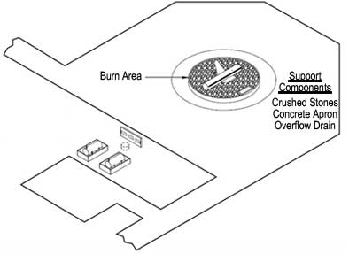
Figure 1. Basic components of a firefighting training area (US DOT 2010).
Aqueous film-forming foams (AFFFs) containing PFCs have been demonstrated to be highly effective at fighting hydrocarbon fuel fires as a consequence of their ability to block oxygen and suppress volatile vapors from flammable solvents. Most military facilities that routinely service aircraft maintain firefighting training areas in order to allow emergency personnel to train with AFFFs and other firefighting methods to prepare them to fight actual aircraft fires. Over 575 firefighting training facilities exist at Air Force, Navy, and Army installations around the world.
Aviation firefighting training areas typically comprise a circular pad of crushed rock, fire-resistant concrete or brick, and a drain to catch overflow (Figure 1). Groundwater data collected in 1999 at Wurtsmith Air Force Base (Michigan), Tyndall Air Force Base (Florida) and Naval Air Station Fallon (Nevada), where PFC concentrations ranged from below detection limit to over 14,000 µg/L, suggest that any military site where AFFFs have been used is likely to have a dissolved plume containing PFCs.
The chemical properties of PFOS and PFOA inhibit most conventional treatment approaches. The strong carbon-fluorine bond and the shielding of the carbon-carbon bonds by fluorine atoms, each with three pairs of non-bonding electrons, contribute to the stability of terminal PFCs and increase their resistance to degradation. Past studies have indicated that these terminal PFCs are recalcitrant to a range of conventional treatments including bioremediation, ozonation, ZVI reduction, and Fenton’s chemistry reactions, or are not possible to treat in situ.
The ERDC/Purdue study chose heat-activated persulfate oxidation modeled upon the successful experimental application of UV radiation-activated persulfate (appropriate for only ex situ treatment) on a laboratory scale. Past studies with UV-activated persulfate have indicated rapid degradation of PFOA in aqueous solution by persulfate radicals with half lives of about one hour. Degradation products included fluoride ions, sulfate ions, carbon dioxide, and shorter chain perfluorinated alkyl acids (PFAAs), which can be further degraded sequentially by persulfate radicals. Persulfate requires a relatively low soil oxidant demand and promotes the formation of free radicals such as the sulfate radical anion (SO4-°) and hydroxyl free radical (OH°), which are highly stable under normal subsurface conditions and travel effectively through the subsurface into target contaminant zones. However, degradation of fluorinated compounds may also result in the production of hydrofluoric acid, which could hinder further the activated persulfate process.
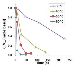
Figure 2. Oxidative degradation of PFOA (100 µg/L or 0.241 µM) by 10,000 mg/L sodium persulfate in unbuffered solutions at temperatures ranging from 30°C to 60°C.
Glass reaction vials (40-mL) contained aqueous solutions of either PFOS or PFOA at a concentration of 50, 100, 500, or 2,500 µg/L and persulfate concentrations from 0 to 20,000 milligrams per liter (mg/L). Oxidant concentrations were chosen based on previous work conducted with contaminants of emerging concern. Well-mixed samples were exposed to temperatures ranging from 20°C to 60°C for up to 336 hours. Changes in PFOA and PFOS concentrations, as well as any detected metabolites, were quantified.
PFOA was degraded by heat-activated persulfate, and higher temperatures resulted in quicker removal (Figure 2). Higher persulfate concentrations were also found to lead to more complete removal of PFOA and shorter-chain PFAAs, with most successful results achieved with a persulfate concentration of 20,000 mg/L at 50°C (Figure 3). At 1,000-2,000 mg/L persulfate, about half of the original experimental PFOA concentration remained after 48 hours. Though pH declined with higher persulfate concentrations, lower pH had no appreciable effect on the results.
Heat-activated persulfate degradation of PFOA produces increasingly shorter chain PFCs, one carbon difluoride (CF2) group at a time referred to as an "unzipping" process. Intermediate products recovered during the degradation process included perfluoroheptanoic acid, perfluorohexanoic acid, perfluoropentanoic acid, perfluorobutanoic acid and trifluoroacetic acid. Most of the intermediates were degraded with 10,000 mg/L persulfate after 72 hours at 60°C and after 48 hours at 50°C, with only the primary metabolite, trifluoroacetic acid, remaining.
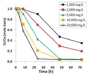
Figure 3. Oxidative degradation of PFOA (100 µg/L or 0.241 µM) by sodium persulfate concentrations ranging from 1000 mg/L to 20,000 mg/L at 50°C in unbuffered solutions.
Addition of 1,000 µg/L ethylbenzene, as a representative hydrocarbon common to military sites, to PFOA samples with 10,000 mg/L persulfate did not reduce PFOA degradation rates. Based on these findings, it is expected that elevating persulfate concentrations would lead to degradation of PFOA and certain hydrocarbon-based contaminants. In addition, using a single application of 10,000 mg/L persulfate effectively degraded 6:2 fluorotelomer sulfonate, a precursor compound commonly found in AFFF mixtures, suggesting that heat-activated persulfate treatment may effective in degrading compounds produced through the fluorotelomerization process.
The study found that activated persulfate, though feasible to use in the field at concentrations examined, did not lead to degradation of PFOS. The recalcitrance of PFOS to treatment presents an issue, since both PFOS and PFOA are found in AFFFs and are likely both present in groundwater where AFFFs were used. One potential solution may be the use of ZVI amended with a catalyst such as palladium. Preliminary research on using 0.1-0.5 g ZVI with 1-2% palladium at room temperature to degrade both PFOA and PFOS showed promising results. Degradation of both PFCs up to 43% within 48 hours was achieved at room temperature with 0.1 g ZVI and 1% palladium. The method may be appropriate to in situ application in permeable reactive barriers. The method is being studied further as a new SERDP (Strategic Environmental Research and Development Program) project ER-2426 to optimize the properties of nano-bimetals for increased reactivity and delivery within zones of PFC-contaminated groundwater.

New Remediation Technology: Treating 1,4-Dioxane with Synthetic Media
Contributed by Thomas K.G. Mohr, University of California-Davis, and Frank R. Niles Massachusetts Department of Environmental Protection
A synthetic media system using a carbonaceous adsorbent has operated at an industrial site in Waltham, Massachusetts, since late 2011 to treat 1,4-dioxane in extracted groundwater. The system was installed due to inability of an existing air stripper to reduce the 1,4-dioxane to concentrations below the State's 0.3 µg/L discharge limit for 1,4-dioxane. Since integrating the synthetic adsorbent, 1,4-dioxane has been detected above the laboratory detection limit in the facility's effluent only once. Chlorinated VOCs also have consistently met discharge limits during the same operating period.
1,4-Dioxane is a contaminant of emerging concern that is most commonly found at sites where 1,1,1-trichloroethane (TCA) was used as a vapor degreasing agent. It was added to TCA as a stabilizer. 1,4-Dioxane's apparent widespread occurrence at industrial sites also is attributed to its use in manufacturing processes, such as those used to produce polyester resin and polyethylene terephthalate plastics, cellulose acetate membranes, and some pharmaceutical products.
1,4-Dioxane is classified as a probable human carcinogen by the U.S Environmental Protection Agency (EPA), and it has toxic effects on the kidney and liver. EPA’s 2010 toxicological review of 1,4-dioxane recommended a steeper cancer slope factor, resulting in a 2012 health advisory level for 1,4-dioxane of 0.35 micrograms per liter (µg/L). Accordingly, several states (including Massachusetts) have lowered their drinking water advisory levels and site cleanup levels for 1,4-dioxane.
Data supporting EPA's third Unregulated Contaminant Monitoring Regulation identified 1,4-dioxane at concentrations greater than the prescribed Method EPA 522 method detection limit (0.07 µg/L) in 11.9% of 7,171 samples from 851 public supply water sources. This rate of detection is exceptionally high for an organic anthropogenic contaminant in drinking water. While the concentrations detected are generally very low, 3.9% of water systems tested have 1,4-dioxane detections exceeding the EPA health advisory level (0.35 µg/L). The widespread occurrence of 1,4-dioxane in drinking water reflects its ubiquitous presence in groundwater.
Treating 1,4-dioxane is a challenge due to its very low Henry's law constant and complete miscibility. It also has a low organic carbon-water partition coefficient (KOC) and is immune to abiotic breakdown under ambient conditions. 1,4-Dioxane is generally resistant to natural biodegradation at meaningful rates. Similarly, air stripping is ineffective, and effectiveness of granular activated carbon (GAC) is limited at high flows and low concentrations due to 1,4-dioxane's low KOC.
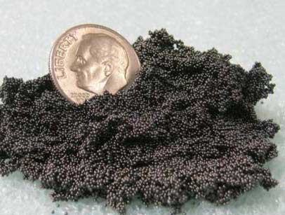
Figure 1. Carbonaceous adsorbent, with non-dusting spherical form.
The primary solution for 1,4-dioxane remediation has been various forms of ex situ advanced oxidation. Pump and treat technology followed by ex situ treatment with catalyzed ultra-violet light oxidation technology (such as PhotoCAT™) or ozone peroxidation technology (such as HiPOx™ or ClearDioxane™) has been favored. These systems require careful monitoring and maintenance to adjust for variable source water and operating conditions. Challenges include onsite ozone generation, delivery and storage of hydrogen peroxide, frequent change-out of costly ultraviolet lamps, pH sensitivity, possible formation of bromate or hexavalent chromium, and competitive consumption of free radical scavengers such as alcohols, acetone, and iron as well as carbonate alkalinity.
The carbonaceous adsorbent used at the Massachusetts facility has demonstrated success in removing 1,4-dioxane occurring in a wide range of concentrations for water treatment elsewhere. The product (AMBERSORB™ 560) is produced through partial pyrolysis of a sulfonated styrene-divinylbenzene copolymer, which yields a hard adsorbent with high surface area and high porosity (Figure 1). When compared to broad-spectrum GAC, which consists of non-synthetic material, this adsorbent provides more specificity and selectivity for many non-polar compounds. As an engineered product, it offers lower batch-to-batch variability in adsorption capacity.
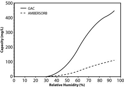
Figure 2. Water adsorption isotherm for GAC versus synthetic media.
Studies by the manufacturer suggest that the material's effectiveness relates to its transitional pores, pore shape, and smaller particle size, as well as its higher hydrophobicity when compared to GAC (Figure 2). This is a significant advantage in vapor-phase applications for removal of volatile organic compounds (VOCs) because the product retains its capacity in high-humidity vapor streams. The lower adsorption potential of water results in a net higher adsorption potential for non-polar compounds. In liquid-phase applications, this hydrophobicity contributes to the higher sorption capacity for organic contaminants, including 1,4-dioxane and chlorinated VOCs. Although 1,4-dioxane is miscible in water, it is both a non-polar and polar solvent due to its transitional dipole moment and dielectric constant in different conformations. Vendor comparisons also suggest the adsorption capacity of the synthetic media is roughly an order of magnitude higher than GAC at the lower end of the equilibrium concentration range (Figure 3), the range of 1,4-dioxane concentrations typically encountered in contaminated groundwater.
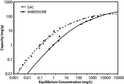
Figure 3. GAC and synthetic material adsorption isotherms for 1,4-dioxane.
For most 1,4-dioxane treatment systems using this product, a total of three adsorbent beds is preferred to provide continuous treatment (Figure 4). During operation, the dioxane-laden groundwater passes through two online beds until breakthrough occurs at the lead vessel. The lead vessel is then taken offline for regeneration. The lag vessel is placed in the lead position and the standby vessel is placed in service in the lag position.
In contrast to GAC, this adsorbent is typically regenerated in place, using low-pressure steam. Regeneration of the offline bed is usually accomplished by passing low-pressure steam through the bed, countercurrent to the direction of the process stream flow. After exiting the bed, the steam/1,4-dioxane flow is condensed and decanted. Upon regeneration with 10 to 12 pore volumes of steam, the bed is returned to the standby position.
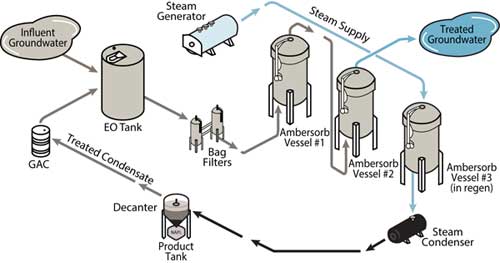
Figure 4. Typical process flow using AMBERSORB adsorbents for groundwater treatment.
To further minimize the waste volume needing offsite disposal, the highly concentrated condensate from the steam regeneration process is often "superloaded" through a small vessel containing GAC. Although GAC has a relatively low adsorptive capacity for low concentrations of 1,4-dioxane, a relatively high adsorptive capacity exists at the elevated 1,4-dioxane concentrations present in the condensate (Figure 3). Processed water from the superloader is directed back to the head of the pretreatment train and the small GAC vessel is periodically sent offsite for reactivation.
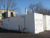
Figure 5. Storage units containing the synthetic media system used at the Waltham site.
At the Waltham site, this synthetic media system treats 15 gallons per minute (gpm) of groundwater to address a targeted portion of the groundwater plume. The groundwater contains an average 1,4-dioxane concentration of 20 µg/L and total chlorinated VOC concentration of 3,000 µg/L. Water is pumped in an up-flow mode through multiple synthetic media vessels operated in series. The system is housed inside two portable storage containers (Figure 5).
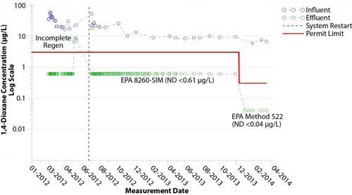
Figure 6. Influent and effluent 1,4-dioxane concentrations at the Waltham site.
Since synthetic media operations started, 1,4-dioxane concentrations in the effluent have been consistently non-detect at <0.61 µg/L, with one exception (Figure 6). After changing to EPA Method 522, the 1,4-dioxane concentrations in the effluent also have been consistently less than the analytical laboratory’s method detection limit (<0.04 µg/L). In addition, chlorinated VOCs have been consistently removed to concentrations below 1.0 µg/L for the entire 26-month operating period.
Replacement of the site's existing 100-gpm air stripper with a full-scale synthetic media system is anticipated to be complete by September 2014 to address other portions of the groundwater plume. Cost analysis of alternatively positioning an AMBERSORB unit after the existing air stripper showed that use of the synthetic media, alone, would be more cost-effective in removing the 1,4-dioxane as well as the VOCs at a comparable rate of throughput.
To be published fall 2014: Woodard, S., Mohr, T.K.G., and Nickelsen, M., 2014. Synthetic Media: A Promising New Treatment Technology for 1,4-Dioxane. Remediation Journal, J Wiley.

Full-Scale Treatment: Electrical Resistance Heating Resolves Difficult Removal of CEC Source Area
Contributed by Sunny Becker, Washington Department of Environment, and Lynette Stauch, TRS Group, Inc.
Cleanup at the Fox Avenue site in Seattle, Washington, has involved implementing several pilot- and full-scale technologies over the past 20 years to address soil and groundwater contamination from numerous chemicals, including contaminants of emerging concern (CEC) such as tetrachloroethylene (PCE), trichloroethylene (TCE), pentachlorophenol (PCP), and dioxins. Full-scale in situ thermal technology involving electrical resistance heating (ERH) was applied in early 2013 after limited success with other technologies to address a significant source area with dense non-aqueous phase liquid (DNAPL) extending 65 feet below ground surface (bgs). Analysis of over 200 samples in late 2013 indicated that ERH use resulted in a 99% reduction of the estimated mass of contaminants of concern (COCs) in the primary source area and significant COC reductions (more than 90% overall) in the associated dissolved plume. Bioremediation as a polishing step is now progressing; residual subsurface heat in the treatment area is promoting reductive dechlorination of contaminants, and injections of emulsified soybean oil scheduled to begin later this year are expected to further enhance declorination in the source area as well as the downgradient plume. Control of this 500-foot-wide groundwater plume is critical in preventing recontamination of seeps that discharge groundwater into the Lower Duwamish Waterway Superfund site.
The Fox Avenue site occupies about 2.5 acres in an industrial area of south Seattle. Since the late 1930s, the site (previously known as Great Western Chemical) has been home to coke- and oil-fired furnace operations followed by chemical/petroleum product blending, repackaging and distributing facilities. In addition to PCE, TCE, and PCP, primary COCs in groundwater include cis-dichloroethene (cis-DCE), vinyl chloride, total petroleum hydrocarbons (TPH, including mineral spirits) and BTEX (benzene, toluene, ethylbenzene, and xylenes). Groundwater flows at an estimated rate of 0.1 to 2 feet per day from the site and discharges to the Lower Duwamish Waterway at a point 400-500 feet downgradient. The lithology consists of sands and silts overlaying a confining silt layer that creates a perched aquifer extending from 10 feet to 75 feet bgs. DNAPL was observed in wells.
Remedial actions began in 1990 with the removal of underground storage tanks. From 1995 through1996, a soil vapor extraction system (SVE) and a groundwater pump and treat system operated on a pilot-scale basis. Minimal reductions in COC concentrations prompted additional investigations and pilot testing of chemical oxidation using potassium permanganate as well as dual-phase extraction from 1997 through 2000. Peroxide injection and biosparging were recommended in a 2000 supplemental feasibility study but not implemented. In 2005 and 2006, three rounds of permanganate injection and expansion of the SVE system resulted in additional COC concentrations reductions in soil as well as groundwater; however, significant COC rebound was observed in the groundwater by 2007.
Monitoring indicated that naturally-occurring reductive dechlorination was occurring in the groundwater plume but persistently stalled, generating significant concentrations of cis-DCE and vinyl chloride. Enhanced reductive chlorination (ERD) was initiated in 2009 through injections of waste sugar, a solution of sucrose and other carbohydrates derived from off-specification food-grade sugars. Between 2009 and 2013, 10 injection events at various locations were administered to intersect the plume and reach the entire depth of the aquifer.
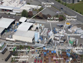
Figure 1. Locations of ERH electrode field and supporting remedial equipment at the Fox Avenue site.
Extensive source area characterization (including membrane interface probe profiling) also was conducted in 2009 to determine the final remedy for source area soils, which were estimated to still contain approximately 10,000 pounds of solvent mass. ERH technology was selected to treat soils in the primary source area. The ERH system was designed to treat approximately 42,000 cubic yards of soil with the remedial goal of achieving a combined average concentration of 10 mg/kg PCE and TCE. Prior to ERH application, the average PCE + TCE concentration was 141 mg/kg in a treatment area that included the vadose zone soil, upper silt horizon and lower silt horizon with spot concentrations exceeding 4,000 mg/kg.
The ERH design anticipated that the completed waste sugar injections would enhance reductive dechlorination in the groundwater plume onsite and downgradient. The design also accommodated conditions and infrastructure supporting ongoing industrial activities, including deep contamination below an active building, shallow contamination under an active rail spur, utility corridors, existing stormwater management trenches, and closed tanks (Figure 1). Other influential factors included the presence of mineral spirits, high groundwater flux, variability in soil resistivity values (such as 40-120 ohm-meter versus 5-18 ohm-meter), and effective recovery of steam and vapors released from deeper soils.
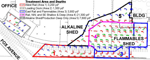
Figure 2. Five treatment areas distinguished by site conditions and past activities; ERH treatment was designed to reach shallow depths in areas 1 through 3, shallow and deep soils in area 4, and only deep (65 feet bgs) soil of area 5.
Hollow-stem auger drilling was used to install a total of 158 ERH electrodes at an average spacing of 15 feet in five distinct treatment areas (Figure 2). Forty-four electrodes were installed within below-grade trenches, which allowed the facility to continue operating in all but one area. Facility operations were suspended in the treatment area having the majority of existing mineral spirits ("Area 4"); in this area, density of the electrodes was doubled to increase the energy intensity and associated volatilization during ERH. To address soil under the rail spur and building, the electrodes were placed at an angle (Figure 3).
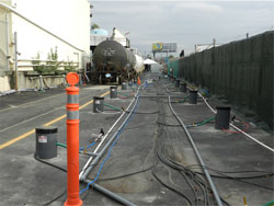
Figure 3. Electrode placement below railroad spur and building.
The ERH system included nine field transformers applying an average operating power input of 1,410 kW, as well as 140 subsurface temperature sensors. Vapors from the boiling liquids were recovered in a steam and air flow averaging 1,500 standard cubic feet per minute (scfm) and separated into two separate streams that were handled by two condensers operating in parallel. Vapors from the treatment area with the highest COC concentrations were then treated by thermal oxidization with an acid gas scrubber, and vapors from other areas were treated in granular activated carbon (GAC) vessels. The generated water was discharged to the sanitary sewer under a King County discharge permit.
Active heating began in early January 2013 and ended in the middle of May 2013, when the average subsurface temperature reached a maximum of 99.2°C. Heating rates were highest during the initial two months (Figure 4). Various system parameters were monitored throughout operations, including time, energy input, subsurface temperature, extracted vapor concentrations and steam/condensate production. Use of a dynamic soil sampling strategy enabled heating shutdown in an area where cleanup goals were met, which allowed heating efforts to be redirected into other areas still containing elevated CVOCs. Over the full operating period, a total of 7.2 megawatts of power was applied to the subsurface. Approximately 66% of the power was applied in Area 4, where approximately 80% of the estimated source-area contaminant mass existed.
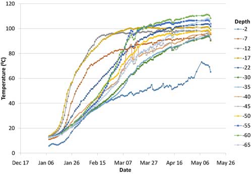
Figure 4. Rate of soil heating during ERH application in 2013.
Performance evaluation indicated ERH treatment removed approximately 10,000 pounds of chlorinated solvents and over 19,000 pounds of mineral spirits, based on pre-ERH estimates. Of the mineral spirits, 10,330 pounds of TPH was removed through the GAC vessels and 9,230 pounds of TPH was destroyed through the thermal oxidizer. During the 4.2 months of ERH operations, the average combined PCE and TCE concentration in soil decreased from an average of 141 mg/kg to 0.53 mg/kg, a 99.9% removal of estimated mass in the source area (Figure 5). As expected, the remaining PCE and TCE exist in the area exhibiting the highest pre-ERH concentrations (Figure 6). Limited sampling at one location also indicated an unexpectedly high (65%) reduction in PCP concentrations in soil. Although ERH implementation focused on soil remediation, it also reduced PCE + TCE concentrations in groundwater by about 90% immediately following active heating, with further reductions observed in subsequent months during the cool-down phase.
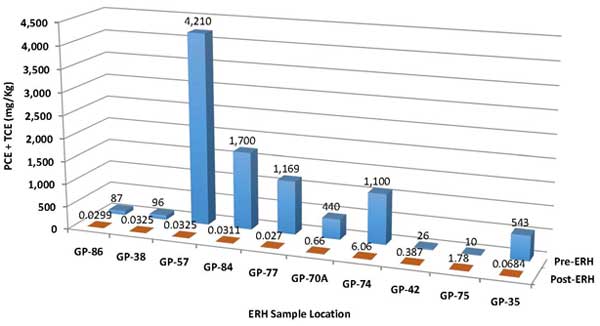
Figure 5. Comparison of PCE + TCE concentrations in soil before and after ERH application.
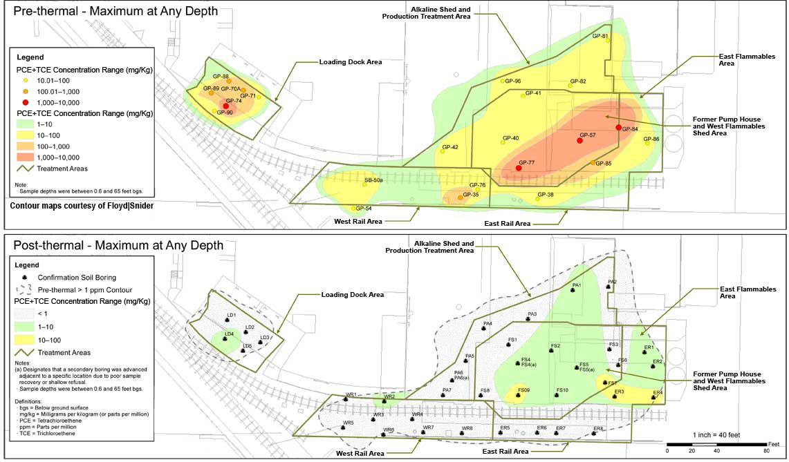
![]() Figure 6. Site-wide reduction in PCE + TCE concentrations due to ERH application.
Figure 6. Site-wide reduction in PCE + TCE concentrations due to ERH application.
Post-heating groundwater samples collected via Geoprobe® drilling equipment have been used to establish groundwater conditions and plan injection of emulsified soybean oil (ESO) to stimulate anaerobic microbial processes for additional dechlorination of CVOCs in groundwater. Temperature trends indicated that the optimum temperature for ERD (35-40°C) was reached in approximately 12 months after ERH shut down. Fourteen new injection wells and two existing injection wells have been installed for administering ESO later this year as a source-area remediation polishing step and to promote ERD in a corner of the downgradient groundwater plume.
Indoor air of facilities operating onsite and at a nearby property continues to be tested to ensure that the State of Washington cleanup standards are met for PCE and TCE as well as vinyl chloride. Onsite and targeted offsite sampling in 2009 and 2010 had identified PCE and TCE vapor intrusion at several locations. In 2013, the State's standards for these indoor contaminants were adjusted to reflect EPA's new toxicity information.
A four-well SVE system will be used in a northwest corner of the site to remove PCE remaining in the vadose zone, which would otherwise act as a long-term source of groundwater contamination. Existing asphalt or cement caps on approximately 90% of the site's ground surface prevents direct contact with soil contaminants, including dioxins and residual PCP, that will remain onsite with deed restrictions.
RESOURCES
CLU-IN Website: Contaminant Focus
This issue area of CLU-IN bundles information associated with the cleanup of individual contaminants and contaminant groups. The information is presented in categories such as policy and guidance, chemistry and behavior, environmental occurrence, toxicology, detection and site characterization, and treatment technologies. Contaminant and contaminant groups addressed in this online area include CECs, such as arsenic, chromium VI, 1,4-dioxane, dioxins, perchlorate, polychlorinated biphenyls, and trichloroethylene.
Fact Sheet Series: Emerging Contaminants and Federal Facility Contaminants of Concern
EPA recently updated a series of technical fact sheets addressing contaminants of concern that present unique issues and challenges at contaminated federal facility sites. Each contaminant-specific fact sheet briefly summarizes the compound's physical and chemical properties, its environmental and health impacts, related federal and state guidelines, and applicable detection and treatment methods. Contaminants addressed by these fact sheets include: 1,2,3-trichloropropane (TCP); 1,4-dioxane; 2,4,6-trinitrotoluene (TNT); dinitrotoluene (DNT); hexahydro-1,3,5-trinitro-1,3,5-triazine (RDX); N-nitroso-dimethylamine (NDMA); perchlorate; polybrominated diphenyl ethers (PBDEs) and polybrominated biphenyls (PBBs); tungsten; nanomaterials; and perfluorooctane sulfonate (PFOS) and perfluorooctanoic acid (PFOA).
New Edition: Superfund Remedy Report
EPA's Office of Superfund Remediation and Technology Innovation released the 14th edition of the Superfund Remedy Report. The report compiles data on overall remedy selection and remedies for source materials (such as soil and sediments), groundwater, and surface water since 1982, with a focus on Superfund remedial actions selected in fiscal years 2009 through 2011. This edition also documents the types of remedies selected for sediments and vapor intrusion mitigation.
Recent Interagency Meeting: FRTR Meeting on Emerging Contaminants
The Federal Remediation Technologies Roundtable (FRTR) works to build a collaborative atmosphere among federal agencies involved in hazardous waste site cleanup. Since 1990, the FRTR has strived to share information about cleanup technologies; discuss future federal directions of site remediation programs and their impact on the technology market; interact with similar state and private industry technology development programs; and form partnerships to pursue subjects of mutual interest. At its November 2013 meeting, the FRTR focused on emerging contaminants and related issues; a summary of the meeting and individual presentations are available from the FRTR website.
New Guidance: Groundwater Remedy Completion Strategy; Moving Forward with the End in Mind
EPA's Office of Superfund Remediation and Technology Innovation partnered with the Agency's Federal Facility Restoration and Reuse Office in developing a new guidance document, Groundwater Remedy Completion Strategy. The guidance is intended to help focus resources on the information and decisions needed to effectively complete groundwater cleanups involving active and/or passive groundwater restoration remedies under CERCLA. Topics addressed in the guidance include design of site-specific remedy evaluations, development of performance metrics and collection of associated monitoring data, and a process for conducting remedy evaluations.
Chemical Assessment: TSCA Work Plan Chemical Risk Assessment; Trichloroethylene: Degreasing, Spot Cleaning and Arts & Crafts Uses
In June 2014, EPA released a final risk assessment for TCE. The assessment identified health risks from TCE exposures to consumers using spray aerosol degreasers and spray fixatives. It also identifies health risks to workers when TCE is used as a degreaser in small commercial shops and as a stain removing agent in dry cleaning. The final TCE risk assessment was developed as part of the Agency's Toxic Substances Control Act (TSCA) Work Plan, which identified chemicals for review and assessment of potential risks to human health and the environment. TCE is the first chemical to complete the work plan risk assessment process under TSCA.
Contact Us:
Suggestions for articles in upcoming issues of Technology News and Trends may be submitted to
Linda Fiedler via email at fiedler.linda@epa.gov.
Past Issues:
Past issues of the newsletter are available at http://www.clu-in.org/products/newsltrs/tnandt/.
Archives | Subscribe | Change Your Address | Unsubscribe


