
- Featured Articles
- Vapor Intrusion Associated with Multiple Contaminant Sources
- Evaluation of Vapor Intrusion in Complex Geologic Setting
- Petroleum Vapor Intrusion Assessment: Multiple Lines of Evidence Lead to Mitigation at Utah Gasoline Fueling Station
- Resources
- New EPA Guidance: OSWER Technical Guide for Assessing and Mitigating the Vapor Intrusion Pathway from Subsurface Vapor Sources to Indoor Air
- New EPA Guidance: Technical Guide for Addressing Petroleum Vapor Intrusion at Leaking Underground Storage Tank Sites
- New Tool: Vapor Intrusion Screening Level (VISL) Calculator
- EPA Website: Vapor Intrusion
- NIEHS Superfund Research Program Briefs: Measuring Vapor Intrusion to Estimate Underground Contamination; Developments toward Low-Cost, Unattended Vapor Intrusion Monitoring
- ESTCP Demonstration Projects: Use of Compound-Specific Stable Isotope Analysis to Distinguish Between Vapor Intrusion and Indoor Sources of VOCs; Use of On-Site GC/MS Analysis to Distinguish between Vapor Intrusion and Indoor Sources of VOCs
 Download This Issue in Adobe PDF® Format
(2.40MB/17pp/PDF)
This issue of Technology News & Trends highlights investigation and mitigation of vapor intrusion at or near contaminated sites, with a focus on summarizing how vapor intrusion was addressed at three sites where response actions are underway. Vapor intrusion is the general term given to migration of hazardous vapors from any subsurface vapor source, such as contaminated soil or groundwater, through the soil and into an overlying building or structure. A wide variety of chemical contaminants can give off vapors, which can migrate towards and enter buildings or other enclosed spaces. These vapors can enter buildings through cracks in basements and foundations, as well as through conduits and other openings in the building envelope. Vapor intrusion is a potential human exposure pathway — a way that people may come into contact with hazardous vapors while performing their day-to-day indoor activities. Depending upon building- and site-specific circumstances, indoor concentrations of chemical vapors arising from the vapor intrusion pathway may threaten human health or safety. When human health or safety is threatened by vapor intrusion, response action is warranted.
EPA collaborates with potentially affected stakeholders and with state agencies when evaluating potential vapor intrusion associated with contaminated sites under federal jurisdiction. Some states also maintain their own vapor intrusion programs that may include tailored guidelines, such as the new North Carolina Division of Waste Management Vapor Intrusion Guidance or the Massachusetts Department of Environmental Protection Vapor Intrusion Guidance.
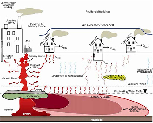
Key Elements of the Conceptual Model of Soil Vapor Intrusion
Source: OSWER Technical Guide for Assessing and Mitigating the
Vapor Intrusion Pathway from Subsurface Vapor Sources to Indoor Air
June 2015


Vapor Intrusion Associated with Multiple Contaminant Sources
Contributed by Rachel Loftin, U.S. EPA Region 9
The Motorola 52nd Street Superfund site in Phoenix, Arizona, encompasses a large contaminated groundwater plume extending approximately seven miles from the former Motorola 52nd Street electronics manufacturing facility where the original release of chemicals occurred. The site also includes several downgradient sources of contamination, including the Honeywell jet engine manufacturing facility. Remediation systems have operated throughout the site since the early 1990s to contain and treat the groundwater and address soil and soil vapor contamination. Over the past four years, site work also has involved evaluating and mitigating vapor intrusion in neighborhoods overlying the plume in the eastern portion of the site.
Trichloroethene (TCE) and tetrachloroethene (PCE) associated with past industrial spills are the primary contaminants of concern. The site is defined by three operable units (OUs) (Figure 1). In OU1, the eastern portion of the plume, the first water-bearing zone is the Basin Fill/alluvium. Here, the depth to groundwater ranges from approximately 20 to 40 feet below ground surface (bgs) and the Basin Fill/alluvium consists of interbedded alluvial silt and gravel that overlie fractured bedrock encountered at approximately 20 to 60 feet bgs. At the Motorola Plant property located in OU1, dense non-aqueous phase liquid (DNAPL) is present in the fractured bedrock. Hydraulic conductivity of the bedrock, which varies from 0.001 to 2 feet per day, is strongly influenced by the presence and frequency of fractures. In OU2, the central portion of the plume, the first water-bearing zone is the Salt River Gravel. Here, the bedrock is encountered at greater depths and the depth to groundwater is between approximately 50 and 75 bgs. In the western portion of the plume, OU3, groundwater is first encountered in the Salt River Gravel at yet greater depths, approximately 75 to 100 feet bgs. Groundwater remediation as well as vapor intrusion evaluation is complicated by northwest to southeast trending bedrock ridges protruding from the alluvium at the northeast portion of OU1 and the southern boundary of OU2.
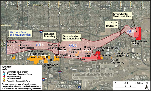
Figure 1. Motorola 52nd St Superfund site groundwater plume as of 2010.
Two groundwater extraction and treatment plants are addressing the volatile organic compound (VOC) plume. The "Motorola 52nd Street Treatment Plant" has treated OU1 groundwater since 1992. As of 2014, this remedy had treated more than 3.6 billion gallons of groundwater and removed more than 24,269 pounds of TCE. Additional treatment has included soil vapor extraction and air sparging systems at OU1 source areas.
The second groundwater treatment plant addresses OU2 groundwater extracted from three wells at the OU2 western boundary downgradient of the Honeywell 34th Street facility, approximately three miles downgradient of the former Motorola facility. As of 2014, the OU2 remedy had treated more than 13.3 billion gallons of groundwater, removed more than 14,000 pounds of VOCs, and contained the OU2 groundwater plume sufficiently to prevent plume migration into OU3. Although not a component of the Superfund remedy, a third treatment system located on the Honeywell 34th Street facility comprises a biologically-enhanced soil vapor extraction system (BSVE) for petroleum hydrocarbons emanating from underground storage tanks leaking jet fuel. From startup in 2009 to 2014, the BSVE system removed more than 10.6 million pounds of petroleum hydrocarbons and 350 pounds of VOCs.
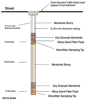
Figure 2. Design of implants for soil gas sampling at the Motorola site.
Since 2011, Freescale (on behalf of Motorola) has conducted an OU1 vapor intrusion evaluation using multiple lines of evidence. First, existing groundwater and soil vapor data and almost two decades of groundwater monitoring data were used to identify areas of elevated TCE and PCE concentrations. Those areas were targeted for additional soil vapor monitoring wells using a "step-out" approach. A field analytical lab was used to expedite field decisions regarding where to place step-out soil vapor wells and when to proceed directly to residential indoor air and sub-slab sampling. Pre-determined subsurface soil vapor, sub-slab and indoor air investigation action levels were established exclusively for the Motorola 52nd Street Superfund site using EPA's regional screening levels and modified soil gas human health screening levels (SGHHSLs) with attenuation factors to reflect specific conditions in Arizona. When the soil vapor data exceeded the SGHHSLs for TCE or PCE and met the soil vapor action level, sub-slab and indoor air were immediately sampled at nearby residences.
The step-out approach for soil gas sampling used baseline data collected from 26 original soil gas sampling points where a SGHHSL was exceeded. Factors affecting selection of step-out sampling from the 26 locations included spacing of nearby sampling locations, magnitude of SGHHSL exceedance and nature of adjoining property. Soil gas sampling at the 26 original sampling points led to 21 "step 1" locations. Of these, eight exceeded a SGHHSL and led to identification of 19 "step 2" locations. This stepwise process continued until "step 4," when sampling indicated no SGHHSL exceedance. Along the study area perimeter, a mobile laboratory also was used to facilitate field decisions regarding step-out sampling where TCE or PCE soil gas concentrations exceeded a SGHHSL. As a result of this process, 53 additional semi-permanent sampling locations were identified and a total of 79 soil gas implants were installed. Each soil gas implant has two microfilter sampling tips emplaced at 5- and 15-foot depths inside a 2- to 4-inch diameter borehole (Figure 2).
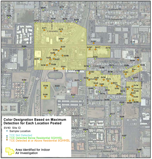
Figure 3. Areas identified for indoor air investigations associated with the Motorola 52nd Street site.
Two consecutive rounds of soil gas sampling were conducted at the 79 implant locations. The samples were collected in air-tight glass syringes and submitted to the mobile laboratory or in SUMMA® canisters that were shipped to fixed laboratories. The analytical results were compared to the SGHHSLs to identify several areas where an investigation of indoor air and sub-slab soil gas was warranted (Figure 3).
As a second line of evidence for the need to sample sub-slab soil gas or indoor air, concentrations of chemicals of concern in groundwater were compared to the soil gas results to identify any correlation and to evaluate whether the data distribution was consistent with the conceptual site model. A comparison of the TCE soil gas concentrations to the TCE concentration contours in groundwater showed a rough correspondence in most areas (Figure 4). Elevated soil gas concentrations in one area of OU1 generally coincided with the location of the subsurface bedrock ridge believed to locally alter groundwater flow directions and unexpectedly create a preferential flow and transport pathway directed to the northwest. In contrast, comparison of PCE soil gas concentrations to the groundwater concentration contours showed a lower correlation.
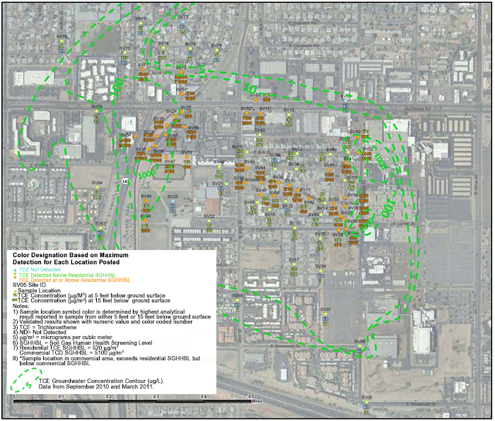
Figure 4. Overlay of OU1 TCE soil gas results (µg/m) and groundwater concentration contours (µg/L).
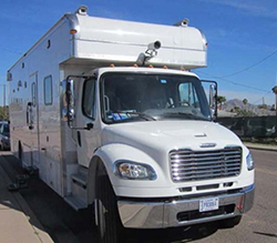
Figure 5. EPA TAGA mobile laboratory operating at the Motorola site.
To date, a minimum of two rounds of indoor air sampling has been completed at 116 locations including four schools and seven commercial buildings, during both cool and warm seasons. Where detected, indoor air TCE concentrations have ranged from 0.13 µg/m3 to 24.0 µg/m.3 A minimum of two rounds (warm and cool season) of sub-slab sampling occurred at residential buildings but not at commercial buildings because underground infrastructure made sub-slab sampling impractical. Where detected, residential sub-slab TCE concentrations have ranged from 2.0 µg/m3 to 43,000 µg/m.3
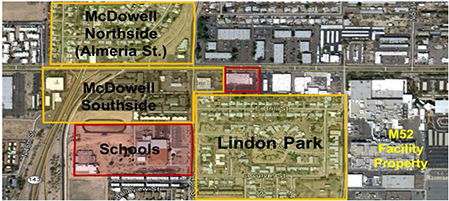
Figure 6. Neighborhoods near the Motorola 52nd Street Plant (also known as the "M52 facility property") that were evaluated for vapor intrusion.
In 2014, the U.S. Environmental Protection Agency (EPA) deployed a trace atmospheric gas analyzer (TAGA) mobile laboratory (Figure 5) to confirm soil gas, outdoor air and indoor air concentrations at OU1 and to determine where the highest existing groundwater and soil gas VOC concentrations in OU1 and OU2 may lead to vapor intrusion. Use of the mobile equipment to collect soil gas samples from temporary soil vapor monitoring wells enabled field staff to quickly access data for field decisions concerning where step-out soil gas samples or indoor air samples should be collected. It also facilitated mitigation decisions by allowing room-by-room indoor air data collection in several homes. In OU2, the TAGA equipment was used to conduct indoor air sampling in a residential area where the temporary soil vapor probe data indicated a potential for vapor intrusion. In OU3, TAGA data helped determine that vapor intrusion is not occurring but identified a small soil vapor plume surrounding an existing soil vapor well in a commercial area. During the TAGA event, an additional 51 soil vapor probes were installed to 15 feet bgs and sampled, eight homes received indoor air room-by-room sampling, and the outdoor perimeter of one home was sampled.
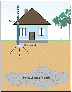
Figure 7. General schematic of a typical sub-slab mitigation system at the Motorola site.
To date, EPA has installed 16 sub-slab depressurization mitigation systems at OU1 residences where indoor air TCE concentrations exceeded the 1.0 µg/m3 indoor air action level specifically established for the Motorola 52nd Street Superfund site. Most mitigation systems are located in the Almeria neighborhood north of the OU1 bedrock ridge and north of McDowell Road (Figure 6).
At the Motorola 52nd Street Superfund site, the sub-slab depressurization mitigation system, which also mitigates radon gas, consists of suction points and a pipe extending from beneath the sub-slab vertically to vent soil gas 1-2 feet above the roof line. A fan attached to the pipe draws the soil vapors through the pipe to discharge to the outdoors (Figure 7). The sub-slab depressurization system includes a manometer and alarm so that homeowners may check and report on its operation. At each home, Freescale conducts operation and maintenance checks of the mitigation system and collects indoor air samples 45-60 days after installation, then semi-annually for two years and annually for the following two years. More frequent checks occur if indoor air results or a homeowner reports an issue with the system.
Seepage of the DNAPL into the system of fractured bedrock under the Motorola facility property at OU1 has made prediction of potential vapor intrusion challenging. For example, residences surrounding the Motorola facility original source areas and one pilot-scale DNAPL extraction well unexpectedly exhibit no vapor intrusion (Figure 8). In contrast, the highest incidences of vapor intrusion are evident where DNAPL is the source of the higher TCE groundwater concentrations leading to higher soil vapor levels, as in the Almeria neighborhood located northwest of the Motorola Plant property and the OU1 bedbrock ridge (Figure 6). A bedrock pilot study to evaluate effectiveness of using groundwater wells to extract the DNAPL is nearly complete. TCE concentration mapping during the first year of the study (Figure 9) showed that pilot-scale groundwater extraction was effectively extracting DNAPL and moderately reducing the groundwater plume in OU1.
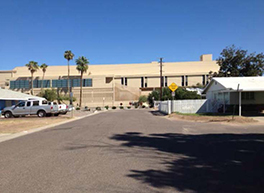
Figure 8. The Motorola 52nd Street Plant, a DNAPL extraction well (at street end) and adjacent homes where TCE vapor intrusion was not detected.
Since 2001 the groundwater table has declined by an average of 16 feet, consequently decreasing the rate of groundwater extraction for treatment at certain remedial extraction wells. The lower groundwater table also may cause localized increases in VOC concentrations in soil vapors. Additionally, groundwater mounding along the bedrock ridge may be leading to soil gas accumulation in neighborhoods located in the vicinity of the bedrock ridge in OU1.
EPA will continue to monitor OU1 homes and apartment units equipped with indoor air mitigation systems through 2016. The OU1 vapor intrusion investigation will begin on the former 90-acre Motorola facility property in the fall of 2015. An OU2-wide vapor intrusion investigation will be conducted in 2015-2016. Completion of final remediation plans for long-term extraction and treatment of groundwater and vapor intrusion, as needed, in both OU1 and OU2 is expected in 2016. The OU1 final remedial investigation will also address DNAPL in bedrock.
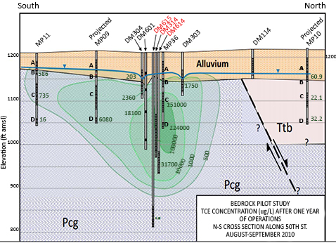
Figure 9. Early findings during the five-year bedrock study of the Motorola site.
Evaluation of Vapor Intrusion in Complex Geologic Setting
Contributed by Mitch Cron and Roy Schrock, U.S. EPA Region 3, and Kevin Kilmartin, Tetra Tech, Inc.
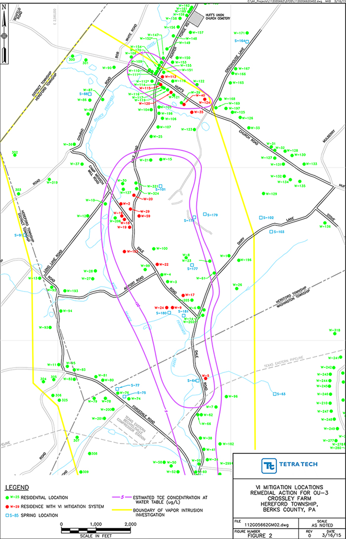
![]() Figure 1. Mapping of estimated TCE concentrations at water table and locations of associated vapor intrusion at residences.
Figure 1. Mapping of estimated TCE concentrations at water table and locations of associated vapor intrusion at residences.
Remediation of the Crossley Farm Superfund site in Berks County, Pennsylvania is focusing on containment and treatment of a groundwater contaminant plume that has migrated offsite, wellhead treatment of impacted residential wells, and vapor intrusion mitigation at residences overlying the plume. The cleanup is challenged by a groundwater flow system that is not yet fully defined and the presence of dense non aqueous-phase liquid (DNAPL) in deep fractured and highly faulted bedrock which juxtaposes various lithologies. An adaptive management approach involving multiple lines of evidence provides a better understanding of the quality of shallow groundwater at and just below the water table and offers flexibility in decisions regarding the need for residential vapor intrusion mitigation systems.
Groundwater surrounding the site is contaminated due to past disposal of drums containing trichloroethene (TCE) likely used as a degreaser for nearby industrial activities. The drums were improperly disposed of at Crossley Farm in a 24-acre area known as Blackhead Hill. Leakage from these drums contaminated groundwater extending approximately 2.5 miles downgradient along Dale Valley (Figure 1). During site investigations, TCE DNAPL and dissolved-phase concentrations as high as 1.3 grams per liter (g/L) were detected in groundwater. A total of 39 different volatile organic compounds (VOCs) have been detected in the source area groundwater.
The region atop Blackhead Hill (including the contaminant source areas) is in a groundwater recharge zone. The site's highlands are underlain by crystalline bedrock, and the adjacent valley is primarily underlain by dolomite. The overburden includes weathered bedrock, saprolite, colluvium and alluvium. Groundwater in the area is generally encountered less than 100 feet below ground surface and occurs within two flow zones comprising geologic units of different lithology but with similar hydrogeological properties. The upper flow zone comprises the soil and saprolite, while the lower consists of the less-fractured, bedrock beneath the saprolite. Interconnected networks of fractures within the bedrock serve as the primary groundwater migration pathways within the lower zone. The vertical extent of the plume is not fully defined due to present inability to identify the base of the groundwater flow system within the fractured bedrock. Beneath the valley, the water-bearing fractures exist as deep as 300 feet.
Hundreds of springs exist along the steep hillsides flanking the valley or close to a creek flowing through the valley. The quality of shallow groundwater discharging onto ground surfaces has been investigated by sampling 13 springs, and TCE has been detected in several springs. Contaminated springs were also discovered discharging directly into several residents' basements. Consequently, the springs are considered one of the potential exposure pathways associated with vapor intrusion. Springs with TCE concentrations of 2-3 micrograms per liter or higher, for example, could produce localized air concentrations equal to levels found in nearby residences. Remedial investigations confirmed that vapors emanating from shallow contaminated groundwater were moving into localized air at some spring locations. As a result, potential risks from the groundwater plume on outside ambient air were evaluated during the subsequent feasibility study. Based on multiple rounds of air sampling, EPA concluded that ambient air at the site does not represent a threat to human health.
Remedial activities at this National Priorities List site began in 1998, when the U.S. Environmental Protection Agency (EPA) uncovered, removed and disposed of approximately 1,200 drums. Approximately 15,000 tons of contaminated soil also were removed. From 2000 to 2010, EPA installed 55 carbon-treatment systems in nearby homes where TCE was detected in private wells at concentrations reaching 2.9 milligrams per liter. In 2012, an onsite groundwater treatment facility began operating to contain the plume. The groundwater is extracted at four extraction wells and treated via vacuum extraction, air stripping and vapor-phase carbon treatment.
In 2006, EPA began sampling the indoor air and sub-slab soil vapor of 24 residences with private wells containing high TCE concentrations and overlying the groundwater plume. In place of risk analysis, venting systems were conservatively installed at the two homes where TCE was detected in indoor air at detectable concentrations.
Follow-on vapor intrusion evaluations at other residences have utilized a three-pronged approach involving analysis of groundwater samples taken from wells and springs, soil vapor samples from the sub-slab of residences and indoor air samples from within residences. The groundwater samples are used to define the local groundwater conditions near the water table in order to evaluate if vapor intrusion is a potential concern. The sub-slab samples were used to determine if VOC vapors from the plume have migrated toward the houses. Results were used to evaluate the extent (if any) to which the sub-slab vapors are migrating into the residence. The results were used to determine whether vapor intrusion could reasonably be expected to threaten human health, defined as an excess cancer risk of greater than 1E-5 (one additional chance in 100,000) or a hazard index of greater than 1 (based on target organ effects). Human health risks were calculated using the actual indoor air concentrations, and/or the sub-slab concentrations, assuming an attenuation factor across the slab of 0.1. In general, 26 of the 39 VOCs (including TCE) that exist in source area groundwater were also detected in sub-slab vapor throughout the extent of the plume. Based on the multiple lines of evidence, vapor intrusion mitigation systems were required at 20 of the 39 residences where sampling was conducted. The multiple lines of evidence consist of: 1) the presence of VOCs in contaminated groundwater underlying the residence (the potential for vapors to exist); 2) the presence of VOCs in the sub-slab vapor samples (proof that the VOCs are partitioning into the vapor phase and migrating to the surface); and 3) direct measurements (indoor air samples) or indirect measurements (sub-slab samples with attenuation factor) to show that vapors exist (or have the potential to exist) at concentrations that are not protective of human health.
EPA has installed systems at 19 of the affected homes; one homeowner chose not to participate in the mitigation program. Since homes in this neighborhood range in age from relatively new (less than 10 years) to well over 200 years, their construction techniques varied widely and prevented application of a standard design for the mitigation systems. Also, many of the older homes include multiple additions of varying ages and construction types, which often triggered the need for multiple mitigation systems within an individual residence.
The mitigation systems commonly involve sub-slab depressurization (radon-type equipment [Figures 2 and 3]), sub-membrane depressurization (including a vapor barrier [Figure 4]), sump hole suction, block wall depressurization, or air cleaning using activated carbon filters. As needed, other installation activities include sealing cinder block or fieldstone basement walls, pouring slabs in homes originally constructed with dirt- or gravel-floored basements (Figure 5), patching existing slabs, and demolishing and replacing some slabs beyond repair. French drains were installed within several slabs to prevent the discharge of contaminated spring water into the basement.
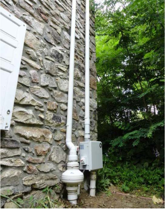
Figure 2. Typical residential exterior exhaust stack for a sub-slab depressurization system near the Crossley Farm site.
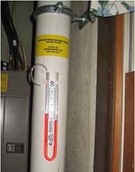
Figure 3. Interior plumbing of the typical sub-slab depressurization systems, including a U-tube manometer providing real-time measurements.
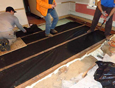
Figure 4. Installation of high-density polyethylene sheets serving as vapor barriers in several homes near the Crossley Farm site.
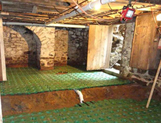
Figure 5. Slab construction using a synthetic base layer into which concrete was poured for homes with basements having dirt floors.
The O&M excludes energy costs, which are borne by the homeowner. The Pennsylvania Department of Environmental Protection (PA DEP) will operate the mitigation systems until the cumulative risk presented by all remaining site-related compounds in sub-slab soil vapor during four consecutive calendar quarters is below a 1E-6 cancer risk level and the non-cancer hazard index is less than or equal to 1. Future re-evaluation of sub-slab soil vapor will begin when maximum contaminant level (MCLs) for TCE and associated VOCs are met in onsite and selected offsite monitoring wells; the current MCL for TCE is 5 µg/L.
The PA DEP and EPA will continue jointly sampling more than 100 local wells and selected springs at least once every two years to determine if more treatment units for well water or indoor air are needed. To avoid future risk, EPA and PA DEP are working with local authorities to implement institution controls such as construction permits that require consideration of potential drinking water and soil vapor contamination, and mitigation measures.
Petroleum Vapor Intrusion Assessment: Multiple Lines of Evidence Lead to Mitigation at Utah Gasoline Fueling Station
Contributed by Robin Davis, Utah Department of Environmental Quality
The Utah Department of Environmental Quality (UDEQ) recently completed an investigation for potential petroleum vapor intrusion (PVI) at the Hoagies Petro Mart V fueling station located in Farr West, Utah, where leaking underground storage tanks (USTs) released gasoline into soil and groundwater. From March 2013 to July 2015, UDEQ used PVI screening criteria similar to that established in EPA's Technical Guide For Addressing Petroleum Vapor Intrusion At Leaking Underground Storage Tank Sites ("PVI Guide") to gain a thorough understanding of the February 2013 release and evaluate the PVI pathway. The potential for PVI was determined highly likely due to presence of free product less than 15 feet below ground surface (bgs) under the site convenience store, and extremely high sub-slab vapor concentrations of total petroleum hydrocarbon (TPH), benzene, and gasoline. PVI was confirmed through collection of indoor air samples from the convenience store in April 2015, which indicated the presence of TPH, gasoline, and benzene vapors at concentrations that exceeded risk-based screening levels. Based on these findings, UDEQ has determined that vapor intrusion mitigation is the next appropriate step.
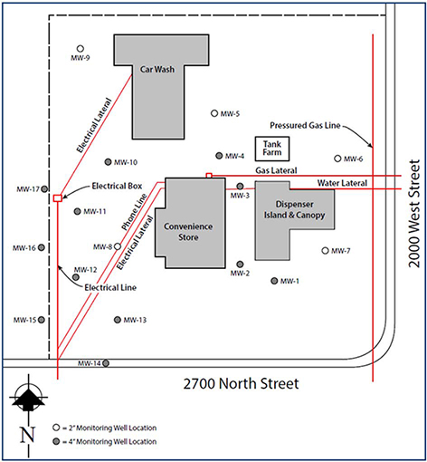
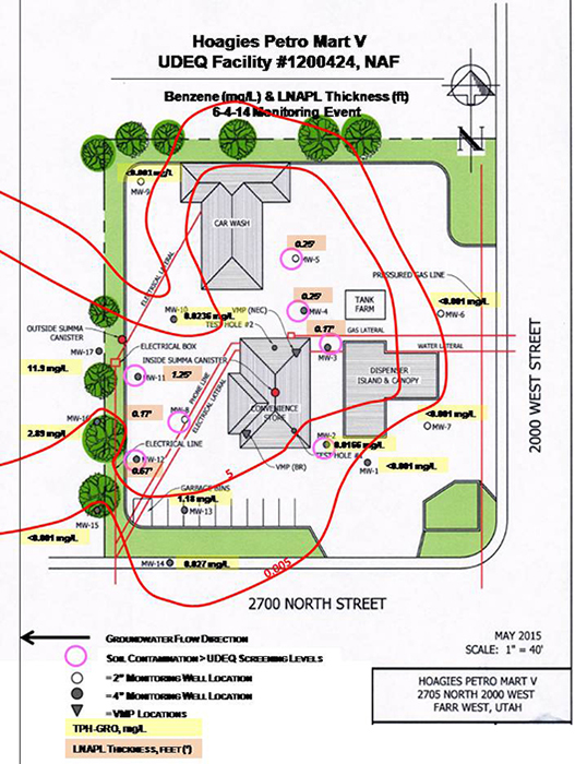
Figure 1. Monitoring well and utility line locations at the Hoagies Petro Mart V site.
The 1.2-acre Hoagies Petro Mart V site consists of a typical 2,400-square foot convenience store built slab-on-grade on engineered fill, a fuel dispenser island with adjacent USTs, a car wash, and areas for driving and parking. The site is bordered by farmland to the north and west, and a major road along with houses to the south and east. A leaking UST was discovered in February 2013 as a result of loss in product inventory (approximately 1,500 gallons of gasoline). The source of the loss was traced to a faulty submersible pump that fits in the UST below ground and pumps product to the fuel dispenser when activated to fill a car's gas tank.
Site investigations began in April 2013. Ten direct-push wells were installed around the property to define the magnitude and extent of groundwater and soil contamination (Figure 1). The wells were installed to a depth of 10 feet below the water table, which ranged from approximately 8 to 14 bgs. Five of the wells were constructed of 15 feet of 2-inch-diameter slotted PVC screen, while the remaining wells used 15 feet of 4-inch-diameter screen. Soil samples were collected from the borings at 5,10,15, and 20 feet bgs at each well location. Groundwater samples were collected from each well for two to four quarters between May 2013 and June 2014. Each water and soil sample was analyzed for total petroleum hydrocarbon-gasoline range organics (TPH-GRO); total petroleum hydrocarbon-diesel range organics (TPH-DRO); MTBE; benzene, toluene, ethylbenzene, and xylenes (BTEX), and naphthalene.
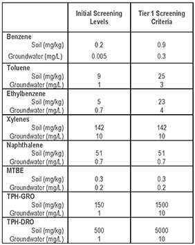
Table 1. Utah's Initial Screening Levels and Tier 1 Screening Levels for benzene, toluene, ethylbenzene, xylenes, MTBE naphthalene, and total petroleum hydrocarbon-gasoline range and diesel-range organics in soil and groundwater.
Results from the initial sampling of soil and groundwater indicated that five of the monitoring wells (MWs) located closest to the fuel dispenser island and convenience store – MW-2, MW-3, MW-4, MW-5 and MW-8 – contained BTEX and TPH-GRO levels exceeded Initial Screening Levels (ISLs) and Utah's Tier 1 Screening Criteria1 (Table 1). Contaminant concentrations exceeding both screening criteria for soil were found at depths ranging from 9 to 30 bgs. A total of 29 soil samples were collected, with benzene exceeding Tier 1 criteria in nine samples, toluene in seven samples, ethylbenzene in three samples, and TPH-DRO in three samples.
Seven additional 2-inch monitoring wells were installed in September 2013 west of the existing wells to further delineate the extent of the contamination and better define site hydrogeology. Four of the wells were installed on the adjacent property. Additional groundwater samples were collected from all wells from September to October 2013. The majority of the wells west of the tank holding location and fuel dispenser island contained BTEX and TPH-GRO, including offsite wells, while one well contained an inch of free product at the water surface. The results indicated westward migration of contaminants with groundwater flow and the presence of contamination underneath the convenience store. Soil samples collected concurrently at all well locations indicated that at a depth of 9 feet, benzene and TPH-GRO were present in soil at concentrations up to 32.4 mg/kg and 5,280 mg/kg, respectively. Benzene and TPH-GRO in groundwater ranged up to 39.1 mg/L and 118 mg/L, respectively. This information prompted the collection of sub-slab vapor samples in June 2014, as well as further concurrent groundwater sampling to better define the extent of the release, determine the potential for vapor intrusion and identify the remediation methods appropriate for the site.
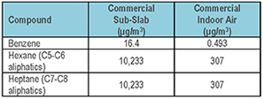
Table 2. Utah's screening levels for compounds in sub-slab soil vapor and indoor air on commercial land.
In June 2014, two sub-slab vapor monitoring points (VMPs) were installed inside the convenience store for collection of soil vapor samples beneath the building foundation and directly above the contamination. Data collected from the VMPs indicated high sub-slab soil vapor concentrations of TPH C5-C8 aliphatics (8.9 and 57 million micrograms per cubic meter [µg/m3]), benzene (17,000 and 850,000 µg/m3) and TPH as gasoline in the C5-C12 aliphatic range (3.5 and 20 million µg/m3). One of the VMPs exhibited a sub-slab soil vapor methane concentration of 72,000 parts per million by volume (ppmv). Contaminant concentrations detected in sub-slab soil vapor underneath the convenience store exceeded Utah's standards for commercial land use (10,233 µg/m3 for TPH C5-C8 aliphatics and TPH as gasoline C5-12 aliphatics, and 16.4 µg/m3 benzene, Table 2), indicating a high potential for vapor intrusion risk.
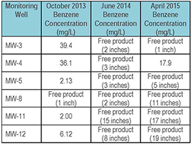
Table 3. The thickness of free product increased between monitoring events in October 2013, June 2014, and April 2015. Wells 3, 4 and 8 are close to the convenience store.
Groundwater samples collected in June 2014 provided an additional line of evidence for high risk of vapor intrusion into the convenience store. Free product was more prevalent than during October 2013, and found in six wells, ranging from 2 to 15 inches in thickness. Though free product was removed from the wells (approximately 97 gallons of groundwater plus free product were recovered) and was not found in July and October 2014, additional product was found in five of the wells in April 2015 ranging from 1 to 19 inches thick (Table 3; Figures 2,3, 4, and 5). Wells were pumped three times to remove the product. Because the initial vertical separation between the free product and the base of the convenience store was less than 15 feet, as recommended in EPA's PVI Guide, it was considered further evidence for the need to install a mitigation system.
Additional sub-slab soil vapor samples, as well as indoor and outdoor air samples, were collected in April 2015 to confirm the presence of PVI and gather the necessary data for selecting an appropriate mitigation system. Indoor air concentrations of benzene, TPH, and gasoline exceeded Utah's risk-based screening levels for commercial buildings (Table 4). One outdoor air sample was collected for eight hours in low wind conditions (northerly wind of 5 miles per hour). Outdoor air contaminant concentrations were lower than those in the indoor air, which ruled out ambient air as the source of indoor air contamination and confirmed PVI from the subsurface source. Two additional pieces of information identified during sub-slab soil vapor sampling in April 2015 provided critical lines of evidence, as specified in the EPA PVI Guide, which confirmed the presence of PVI and helped determine appropriate action. Depleted oxygen and enriched carbon dioxide were evidence of that contamination was biodegrading aerobically but still present. The presence of methane indicated that gasoline is likely unweathered (source weathering is also a screening criterion specified in the EPA PVI Guide).
As an immediate mitigation measure, an indoor air carbon filter treatment system is currently being installed to remove vapors inside the building. In addition, based on indoor air and sub-slab soil vapor samples, as well as the determination that the building slab material is permeable fill (sand as base material for the 4-inch thick cement slab with an 11-12 inch base layer), a pilot test is underway to determine if sub-slab vapors can be removed from points external to the building. This test involves applying a vacuum to existing groundwater monitoring wells around the building and measuring the effectiveness of removing the sub-slab vapors and preventing further PVI. Cleanup technologies being considered to remediate the contaminant source include soil vapor extraction and multi-phase extraction.
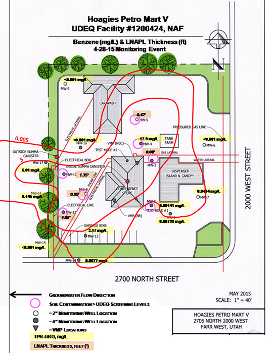
![]() Figure 2. Benzene concentrations and free product (LNAPL) thickness in June 2014. Free product was found in six wells.
Figure 2. Benzene concentrations and free product (LNAPL) thickness in June 2014. Free product was found in six wells.
![]() Figure 3. Benzene concentrations and free product (LNAPL) thickness in April 2015. Free product was found in five wells, with an increase in thickness seen in four of the wells, compared to the June 2014 monitoring event.
Figure 3. Benzene concentrations and free product (LNAPL) thickness in April 2015. Free product was found in five wells, with an increase in thickness seen in four of the wells, compared to the June 2014 monitoring event.
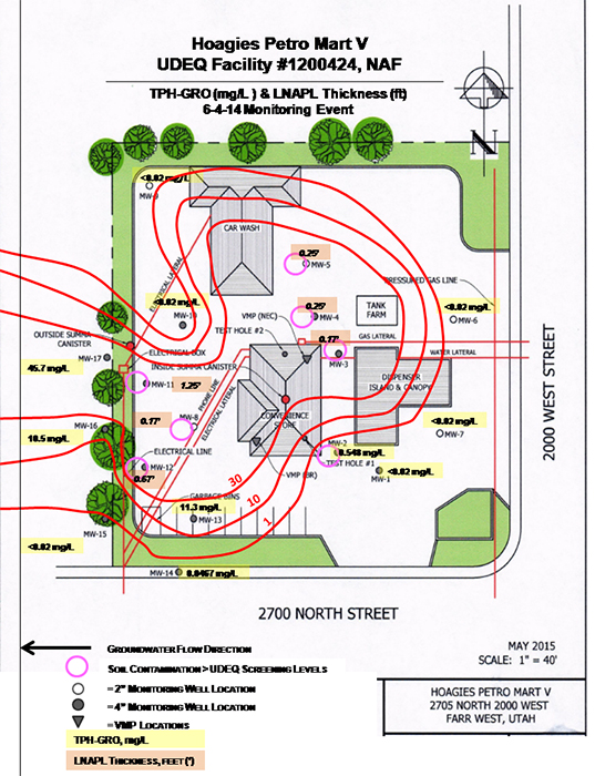
![]() Figure 4. TPH-GRO concentrations and free product (LNAPL) thickness in June 2014. Free product was found in six wells.
Figure 4. TPH-GRO concentrations and free product (LNAPL) thickness in June 2014. Free product was found in six wells.
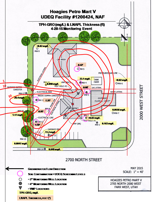
![]() Figure 5. TPH-GRO concentrations and free product (LNAPL) thickness in April 2015. Free product was found in five wells, with an increase in thickness seen in four of the wells, compared to the June 2014 monitoring event.
Figure 5. TPH-GRO concentrations and free product (LNAPL) thickness in April 2015. Free product was found in five wells, with an increase in thickness seen in four of the wells, compared to the June 2014 monitoring event.
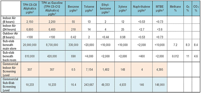
Table 4. Indoor and outdoor air, and sub-slab soil vapor samples collected in April 2015, indicate TPH, gasoline, and benzene levels exceed risk-based screening levels for commercial indoor air (contaminants exceeding screening levels are highlighted).
1 ISLs were derived by selecting appropriate federal/state maximum contaminant levels. Utah's Tier 1 Screening Criteria are risk-based and non-risk based screening levels defined in the Guidelines for Utah's Corrective Action Process for Leaking Underground Storage Tank Sites.
RESOURCES
New EPA Guidance: OSWER Technical Guide for Assessing and Mitigating the Vapor Intrusion Pathway from Subsurface Vapor Sources to Indoor Air
EPA's June 2015 final vapor intrusion guide (OSWER publication 9200.2-154) presents current technical recommendations of the EPA for assessing and responding to vapor intrusion. The guide clarifies topics such as weighing multiple lines of evidence; statutory authorities for preemptive mitigation or other early actions; options for mitigation systems (including their operation, maintenance and monitoring); termination of response actions; and the role of institutional controls in final cleanup plans when subsurface vapor sources are present. The guide is intended for use at any site (and any building or structure on a site) being evaluated by EPA pursuant to the Comprehensive Environmental Response, Compensation, and Liability Act (CERCLA) or the corrective action provisions of the Resource Conservation and Recovery Act (RCRA), EPA's brownfield grantees, or state agencies acting pursuant to CERCLA or an authorized RCRA corrective action program where vapor intrusion may be of potential concern. The guide pertains to all of the various vapor-forming chemicals that may occur as subsurface contaminants at these sites, which include many non-chlorinated compounds (petroleum hydrocarbons, for example) and compounds that are not used as solvents. One of the main purposes of this guide is to promote national consistency in assessing the vapor intrusion pathway at these sites.
New EPA Guidance: Technical Guide for Addressing Petroleum Vapor Intrusion at Leaking Underground Storage Tank Sites
EPA's June 2015 petroleum vapor intrusion guide (EPA 510-R-15-001) focuses on releases of petroleum-based fuels, including petroleum hydrocarbon (PHC) and non-PHC fuel additives, from underground storage tanks (USTs) regulated under Subtitle I of the Solid Waste Disposal Act of 1984, which are typically located at gas stations. The guide may also be helpful when addressing petroleum contamination at comparable non-UST sites. Supporting technical information in the guide addresses topics such as light non-aqueous phase liquid, seasonal and weather effects and vapor intrusion attenuation factors.
New Tool: Vapor Intrusion Screening Level (VISL) Calculator
The Vapor Intrusion Screening Level (VISL) Calculator is a technical resource developed by EPA that: (1) identifies chemicals considered to be typically vapor-forming and known to pose a potential cancer risk or noncancer hazard through the inhalation pathway; (2) provides generally recommended screening-level concentrations for groundwater, near-source soil gas (exterior to buildings), sub-slab soil gas, and indoor air based on default exposure scenarios and default risk management benchmarks; and (3) facilitates calculation of site-specific screening levels and candidate cleanup levels based on user-defined target risk levels, exposure scenarios, and semi-site-specific or site-specific attenuation factors. The VISL Calculator is an MS Excel workbook that was first published online in 2012. It has been updated periodically as new toxicity information became available and was recently updated to coincide with release of the OSWER Technical Guide. To download the spreadsheet calculator, visit EPA's online compendium of technical information.
EPA Website: Vapor Intrusion
EPA's Vapor Intrusion website is a resource for key information on vapor intrusion for both the general public and environmental professionals. The website contains basic information about vapor intrusion, technical and policy documents, tools and other resources to support vapor intrusion investigations. It also provides access to technical reports focused on topics such as conceptual model scenarios for the vapor intrusion pathway and mitigation approaches for vapor intrusion.
NIEHS Superfund Research Program Briefs: Measuring Vapor Intrusion to Estimate Underground Contamination; Developments toward Low-Cost, Unattended Vapor Intrusion Monitoring
The National Institute of Environmental Health Sciences (NIEHS) Superfund Research Program funds university-based multidisciplinary research on human health and environmental issues related to hazardous substances. The central goal of the program is to understand and break the link between chemical exposure and disease. Measuring Vapor Intrusion to Estimate Underground Contamination (Research Brief 238) describes process models developed by Brown University researchers to predict the concentrations of vapors that enter indoor environments. Developments toward Low-Cost, Unattended Vapor Intrusion Monitoring (Research Brief 236) describes an inexpensive vapor intrusion monitoring system developed by NIEHS Superfund Research Program-funded scientists from the chemical sensor company Seacoast Science.
ESTCP Demonstration Projects: Use of Compound-Specific Stable Isotope Analysis to Distinguish Between Vapor Intrusion and Indoor Sources of VOCs; Use of On-Site GC/MS Analysis to Distinguish between Vapor Intrusion and Indoor Sources of VOCs
Two projects on distinguishing vapor intrusion from indoor sources of volatile organic compounds (VOCs) merited the Environmental Security Technology Certification Program (ESTCP) 2014 Project-of-The-Year Award for Environmental Restoration. Use of Compound-Specific Stable Isotope Analysis to Distinguish Between Vapor Intrusion and Indoor Sources of VOCs (ER-201025) demonstrated use of a step-by-step protocol that can provide an independent line of evidence to determine whether or not buildings are impacted by VOCs. Use of On-Site GC/MS Analysis to Distinguish between Vapor Intrusion and Indoor Sources of VOCs (ER-201119) validated a step-wise investigation procedure using portable, commercially available gas chromatograph/mass spectrometer analysis and real-time decision making to distinguish between vapor intrusion and indoor sources of VOCs.
Contact Us:
Suggestions for articles in upcoming issues of Technology News and Trends may be submitted to
Linda Fiedler via email at fiedler.linda@epa.gov.
Past Issues:
Past issues of the newsletter are available at http://www.clu-in.org/products/newsltrs/tnandt/.
Archives | Subscribe | Change Your Address | Unsubscribe
