 A newsletter that provides descriptions and
performance data for innovative source control technologies that have been
applied in the field.
A newsletter that provides descriptions and
performance data for innovative source control technologies that have been
applied in the field.
|
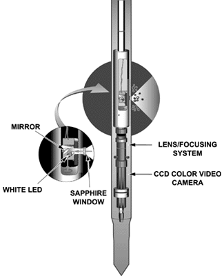
November 2001 Subsurface Soil Analysis Using an In Situ Video Imaging Systemby Stephen H. Lieberman, Space and Naval Warfare Systems Center/San Diego A novel system has been developed by the Space and Naval Warfare Systems Center/San Diego (SSC San Diego) to obtain detailed information about subsurface soil characteristics on very small spatial scales. Known as GeoVIS, this system uses a miniature charge-coupled device (CCD) color video camera coupled with magnification and focusing lens systems integrated into a cone penetrometer probe. The system is designed to characterize soil properties involved in estimating subsurface water flow and contaminant transport, and to characterize complex contaminants such as non-aqueous phase liquid (NAPL). From inside the probe (Figure 1), the small (5-centimeter outside diameter) GeoVIS device uses illumination provided by white light-emitting diodes (LEDs) contained within the probe. The surrounding soil environment is imaged through a flush-mounted, 6.35 millimeter-wide sapphire window on the side of the probe. Video signals from the camera are returned to the surface over a 100 foot-long video cable, where they can be viewed in real time on a video monitor, documented on a video recorder, and digitized if desired. The standard GeoVIS optics system provides a viewing field of approximately 2 by 3 millimeters, and a magnification factor of 100 when viewed on a standard 13-inch monitor. Laboratory testing has shown that this lens system can distinguish particles ranging in size from 1 millimeter to 10 micrometers.
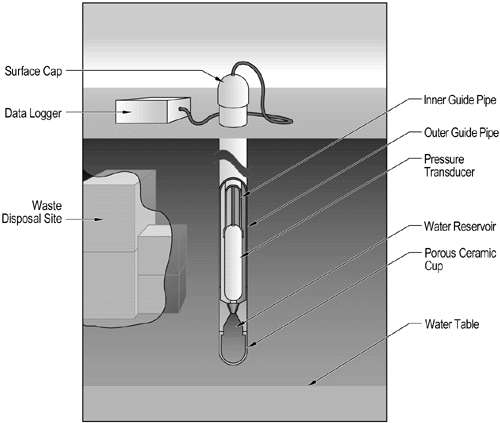
Over the past four years, GeoVIS has been used several times in the area of San Francisco Bay, CA, to characterize NAPL contaminants as part of remedial planning at the former Naval Air Station in Alameda. As a result of aircraft reworking operations occurring at the facility between 1942 and 1997, high levels of fuel hydrocarbons and chlorinated solvents remained in the saturated zone. In particular, maximum concentrations reaching 3,000 mg/kg for trichloroethylene and 640 mg/kg for 1,1,1-trichloroethane were identified. Local geology at the air station comprises primarily fill composed of sand and silty sand overlaying a bay mud, with a depth to ground water ranging from 8 to 10 feet. Direct push methods were used to deploy the camera-equipped penetrometer probe to a depth of approximately 20 feet. A series of 22 pushes was made over a period of 2.5 days to delineate the NAPL zone. Through continuous profiling, a data log on the location of immiscible, separate-phase product was obtained. Resulting data were used to optimize placement of injection and recovery wells for a steam-enhanced contaminant extraction system, and subsequently to verify the extraction system’s effectiveness. This relatively simple, in situ soil characterization technique provides significant advantages over conventional methods involving costly and time-consuming sample collection, offsite laboratory analysis, and variable data extrapolation. Most significantly, GeoVIS provides the small-scale tools needed to identify thin layers of highly permeable material that provide a potential pathway for contaminant transport and which could be missed easily through conventional techniques. Equally important, it provides a direct means for locating contamination source zones that have been very difficult to localize using conventional sampling approaches. Integration of the camera system generally extends the capability of a standard cone penetrometer, which is limited to detecting stratigraphically different and thick soil layers, and can improve the quantification of other optical-based, in situ sensor systems (such as laser-induced fluorescence) used in field screening for petroleum products. Current SSC efforts focus on the development of smaller-diameter camera probes for deployment via light-weight push vehicles, and automated image processing algorithms used for extracting quantitative information (such as soil porosity and percent fuel saturation) from the images. For more information, contact Stephen H. Lieberman (SSC San Diego ) at 619-553-2778 or e-mail lieberma@spawar.navy.mil. Advanced Tensiometers for Vadose Zone Monitoringby John B. Jones, U.S. Department of Energy/Nevada Operations Office The Idaho National Engineering and Environmental Laboratory (INEEL) has developed an advanced tensiometer (AT) for measuring the potential energy status of water in soil and porous rock. For risk assessment at hazardous waste sites, the type of data obtained through AT measurements is important in development of conceptual models and water/contaminant transport models. ATs have significant applications in preliminary site assessments when deployed with other data collection instruments used to measure water content, contaminant concentration, and temperature. Together, these tools provide a comprehensive vadose zone monitoring system. The AT design is a simple, low-cost, and low-maintenance tool, with no moving parts and a pressure transducer that is serviceable from ground surface. The AT operates on the same physical principle as conventional tensiometers to measure how tightly water is held by soil and rock. It contains: (1) a permanently installed porous cup with a water reservoir and guide tube, and (2) a removable pressure transducer (Figure 2). In the fixed-position version, the device is deployed by lowering it into a borehole and bringing the porous cup into good hydraulic contact with the subsurface soil by backfilling. In the portable version, only the weight of the device is used to position the cup. Water in the reservoir then moves through the porous cup until the pressure inside the reservoir equilibrates with the soil moisture pressure in the surrounding soil or rock. The pressure transducer measures the partial vacuum, and a data logger at the surface records the measurement.
Researchers have found that the AT is an effective monitoring instrument when soil water potential is in the range of 0 to -800 centimeters of water pressure, which is the energy status range with the highest hydraulic activity and greatest potential for rapid water movement. These conditions have been found in most deep vadose zones, except those in areas with very low precipitation (less than 6 inches per year). Conventional tensiometers, with pressure gauges located at ground surface, have a practical depth limitation and are affected adversely by barometric pressure and ambient temperature changes. To date, the AT has enabled soil water potential measurements to be taken at depths reaching approximately 150 meters. In contrast, conventional tensiometers are useful at depths of less than 7 meters in most soils and only 3 meters in arid soils. In addition, the AT features a short water column that is isolated from diurnal temperature changes and thus able to stabilize readings. Since 1997, when initial field tests were conducted at INEEL, the AT has been employed at most major U.S. Department of Energy (DOE) facilities to obtain data concerning water movement and subsurface hazardous material. At the Hanford Site near Richland, WA, six ATs in a 7.6 meter-deep lysimeter have been used steadily for the past two years to monitor soil and water pressures in sediments. The AT has demonstrated the ability to continuously monitor soil moisture potential in the vadose zone, and to provide (for the first time) nearly continuous documentation of pulses of water moving deep within soil at the Hanford Site. DOE anticipates that the soil moisture potential data provided by ATs also will be useful in understanding the mechanisms of water movement in the vadose zone and for optimal long-term monitoring and stewardship programs. This project is sponsored by DOE’s Office of Environmental Management/Office of Science and Technology through its Characterization, Monitoring, and Sensor Technology Crosscutting Program. Detailed technical information on the AT is available from Joel Hubbell (INEEL) at 208-526-1747 or jmh@inel.gov, or James B. (Buck) Sisson (INEEL) at 208-526-1118 or e-mail jys@inel.gov. For additional project information, contact John B. Jones (U. S. DOE/Nevada Operations Office) at 702-295-0532 or e-mail jonesjb@nv.doe.gov. More information, including innovative technology summary reports, also is available on the Office of Environmental Management’s web site, www.em.doe.gov.
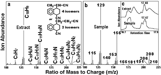
New Compound Identification Technique Uses High Resolution MSby Andrew H. Grange, Ph.D., U.S. EPA/Office of Research & Development/National Exposure Research Laboratory Compounds on the U.S. Environmental Protection Agency’s (EPA’s) priority pollutant lists represent only a small fraction of the toxic compounds that might be found at hazardous waste sites, yet established analytical methods may not be capable of identifying and reporting many of the other compounds. Unidentified compounds may produce errors in the analytical results for known pollutants, and may complicate the interpretation of project data used to assess compliance or perform risk assessments. Currently, gas chromatography/low resolution mass spectrometry (GC/LRMS) is used to analyze many of the compounds listed in EPA’s regulatory appendices. Coelution of multiple components, which can degrade an analytical instrument’s ability to identify and quantitate analytes, is common when a sample contains dozens of compounds. The Environmental Sciences Division of the National Exposure Research Laboratory (NERL) in Las Vegas, NV, has developed a new analytical technique based on high resolution mass spectrometry (HRMS). This technique, ion composition elucidation (ICE), is used to determine the correct elemental composition for compounds containing carbon (C), hydrogen (H), nitrogen (N), oxygen (O), phosphorous (P), or sulfur (S) atoms. In addition to offering more definitive GC/MS analysis of complex samples, ICE provides users with the capability to “fingerprint” waste composition. For example, the chromatogram for an extract of a black, viscous sample from a Superfund site in West Virginia contained several irregular and broadened peaks due to poor resolution of individual peaks. Credible library matches were not found for most of the mass spectra from the compounds producing these peaks. As a result, the identity and quantitation of these peaks using traditional techniques would be highly speculative. The ICE technique was used to identify these compounds, the majority of which contained one or two N and S atoms. Mass spectra presence of a fragment ion that is characteristic of alkylbenzothiazoles (C8H7NS) indicated that most compounds belonged to a common family. The presence of benzothiazoles, which are used in the rubber and dye processing industries, helped to confirm that the waste found at this site had been dumped from a nearby dye manufacturing plant. If additional evidence had been necessary to support legal proceedings, ICE analysis of still-bottom residue from the dye plant could have been used with a high degree of certainty to identify the plant as the waste source. ICE also was integral to “chemical detective work” for the Reich Farms Superfund site near Toms River, NJ. Laboratories using conventional LRMS and HRMS techniques were unable to identify several compounds found in a municipal well located one mile from the site. ICE analysis, however, determined the elemental composition of a molecular ion (C14H14N2) and 10 fragment ions in the well sample’s mass spectrum (Figure 3a). Chemical literature was searched for possible compounds with spectra corresponding to the patterns produced through ICE analysis. The literature suggested that plastics manufacturing based on a 1:2 sytrene: acrylonitrile industrial polymerization process could produce these compounds as byproducts. To evaluate the potential links, a corporation using a similar polymerization process provided a sample for use in comparison to the Reich Farms site sample. The corporate sample yielded a mass spectrum very similar to that of the well water sample at the same retention time (RT) of 17.47-17.48 minutes (Figure 3b). In addition, the 16.7- to 17.9-minute portion of the mass/charge ratio (m/z) 129 ion chromatogram corresponded to the largest peak in the mass spectra for both the corporate sample and the well water extract (Figure 3c). These findings helped to determine that three of the five compounds present in the well water extract also were present in the corporate sample. As a result of the high certainty of a match between the industrial polymerization process and the compounds present in the well water, EPA’s Region 2 office pursued toxicology studies on these compounds.
Figure 3: Mass Spectra Comparison for Reich Farms Superfund Site For more information on the technical details of ICE and its application to these and other analytical problems, visit http://www.epa.gov/esd/chemistry/ecb-posters2.htm, or contact Dr. Andrew Grange (U.S. EPA/NERL) at 702-798-2137 or e-mail grange.andrew@epa.gov.
|
||
|