![]() A newsletter about soil, sediment, and groundwater characterization and remediation technologies
A newsletter about soil, sediment, and groundwater characterization and remediation technologies
This issue of Technology News and Trends highlights cleanup approaches that rely on waste materials or treatment processes as a means to generate heat or other forms of energy for onsite or offsite use. Energy-generating sources can include extracted groundwater already warmed by subsurface temperatures, landfill gas with a high methane content, and soil containing byproducts from coal mining or processing. Recovery of these potential energy sources can help beneficially reuse materials or media that are traditionally treated or discarded as waste and may defray cleanup costs.
Geothermal Energy Used in Groundwater Extraction and Treatment Plants
Online Resources
The U.S. Environmental Protection Agency's (EPA's) Office of Superfund Remediation and Technology Innovation offers Web-based seminars each month on a range of technical and regulatory topics related to site cleanup. Recent topics include Use of Geostatistical 3-D Data Visualization/Analysis in Superfund Remedial Action Investigations and Bioavailability-Based Remediation of Metals Using Soil Amendments. View the calendar of upcoming seminars or access the archives at: www.clu-in.org/training/#upcoming.
Treatment of contaminated soil and groundwater from the Lawrence Aviation Industries (LAI) Superfund site in Port Jefferson, NY, has involved several technologies. Most recently, a full-scale groundwater extraction and treatment system began operating to capture and treat a contaminant plume flowing toward the Long Island Sound. Geothermal energy from the extracted groundwater is collected and used to condition air inside the new water treatment plant rather than gradually lost during the treatment process. When compared to a conventional heat pump, which uses outside air year-round to condition the interior air of a building, the geothermal system provides higher energy efficiency at a lower cost for building operations. It also needs less maintenance than a conventional heat pump, which is typically exposed to adverse weather.
The LAI site was used to manufacture titanium sheeting for the aeronautics industry. Past disposal practices and improper management of drums containing volatile organic compounds (VOCs) such as trichloroethene (TCE) and tetrachloroethene (PCE) as well as hydraulic oils, nitric acids, and other plant wastes resulted in a series of contaminant releases. Investigations in 2003 detected TCE at concentrations reaching 1,100 µg/L in onsite groundwater. Additionally, TCE, PCE, nitrates, and fluoride were detected in onsite monitoring wells and nearby residential wells. The Port Jefferson Harbor, an outlet to the Long Island Sound, lies approximately one mile away in the direction of groundwater flow. Groundwater from the underlying Upper Glacial/Magothy Aquifer is the only source of drinking water in the site vicinity.
Sampling to assess vapor intrusion was conducted at residential properties, businesses, and schools located within the area of the TCE plume. As a precaution, vapor mitigation systems were installed in a few residences and one school. All residential buildings with private wells containing contamination attributed to the LAI site were connected to the public water supply.
Remedial actions involved excavation and offsite disposal of contaminated soil from the LAI site, followed by construction of two groundwater extraction and treatment systems. One system was built at the location of the former manufacturing facility and began operating in September 2010. The second system was constructed one mile downgradient in the residential section of Port Jefferson and started operating in August 2011. Both plants rely on a vertical borehole system to extract groundwater and are equipped with open-loop ground-source heat exchange systems. As needed for all geothermal heat exchange systems, heat loss was minimized during construction by properly sealing all wells and thermally fusing all pipe connections.
The onsite groundwater treatment system uses a conventional 15-hp submersible pump to extract contaminated groundwater from two 10-inch-diameter boreholes at a depth of 250 feet below ground surface (bgs). To assure an adequate seal, each well was constructed of stainless steel (type 304) and packed along its full length with 20% bentonite slurry emplaced using a tremie pipe. Both wells are connected to a header assembly that directs water through approximately 600 feet of HDPE pipe to a single 1.5-ton geothermal heat exchanger inside the treatment plant (Figure 1).
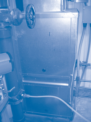
The average temperature of unconditioned groundwater entering the heat exchanger is 56ºF. Following heating or cooling of coils within the exchanger, the air is released at an average rate of 600 standard cubic feet per minute (scfm) and blown through ductwork throughout the plant to supply warm or cool air as needed. This allows the ground below and around the treatment plant to serve as a heat source in winter and a heat sink in summer.
After passing through the heat exchanger, water is pumped to an air stripping system operating with an air/water ratio of 65/1 to separate VOCs from the water. The system is equipped with two 3,000-pound activated carbon filtration vessels to treat the air prior to its emission from the plant. Water then flows from the air stripper through bag filters to extract solid materials generated during the air stripping process, which could plug discharge piping. Finally, the fully processed water is returned to the aquifer through a network of five 258-foot injection wells approximately 1,000 feet upgradient from the extraction wells. The system treats approximately 150 gallons of water per minute.
In contrast, the downgradient groundwater treatment system (within Port Jefferson) extracts contaminated water at a slower rate averaging 80 gallons per minute from four shallower wells at depths of 80-140 feet bgs. The treatment plant operates a similar geothermal energy system and air stripping system. Fully processed water is discharged into an existing pond and its adjoining creek at a point approximately 20 feet from the extraction wells.
EPA Region 2 anticipates operating both treatment plants for approximately 20 years to achieve remedial action goals. Use of geothermal energy is expected to annually avoid 6,000-7,000 kilowatt-hours (kWh) of electricity otherwise needed to heat or cool each treatment plant. This electricity reduction is estimated to save $1,300-$1,700 in annual operation and maintenance costs for each plant. Additional processing efficiencies leading to lower maintenance costs were gained by using variable frequency drives for on-demand rather than continual pumping. Energy-efficient features of the treatment buildings include skylights or strategically placed windows for natural daylighting, tankless water heaters, and highly insulated exterior walls.
Prior to treatment plant start-ups, two injections of potassium permanganate were conducted to address an onsite TCE hotspot by way of in situ chemical oxidation (ISCO). Approximately 42,000 pounds and 31,000 pounds were injected to a depth of 200-220 feet in July and August, respectively, of 2010. Groundwater sampling near the injection locations in January 2011 indicated a 92% decrease in TCE concentrations.
To date, site cleanup costs total approximately $16 million, including about $2 million for the downgradient groundwater extraction/treatment system and $7.5 million for the upgradient extraction/treatment system and ISCO. The cost was reimbursed by $4.7 million in American Resource and Recovery Act funding in 2009. In addition to the geothermal system, other elements of the newer plant in Port Jefferson conformed to the U.S. Green Building Council's Leadership in Energy and Environmental Design (LEED) specifications for new construction and major renovations.
Contributed by Keith Glenn, EPA Region 2 (glenn.keith@epa.gov or 732-321-4454), Maria Jon, EPA Region 2 (jon.maria@epa.gov or 212-637-3967), and Demetrios Klerides, CDM (kleridesd@cdm.com or 212-785-9123)
Superfund Site Landfill Gas Converted to Municipal Energy
EPA Region 5 worked with Waste Management of Illinois, Inc., the Community High School District #117 of Lake County, and other parties in northeastern Illinois to integrate energy production with remediation of the HOD Landfill Superfund site. Landfill gas (LFG) from this inactive waste facility is routed to the adjacent school where microturbines convert methane in the gas to heat and generate electricity for the campus. Prior to the 2003 integration, LFG was treated as waste through active flaring.
From 1963 until 1984, the 51-acre landfill accepted local residential, commercial, and industrial waste. The waste was covered in 1989 with four to seven feet of soil. Over time, portions of the cover exhibited erosion, differential settlement, ponded water, and failing vegetation. Leachate seeps, animal burrows, and fugitive LFG emissions also were evident on or around the cover. By 1990, VOCs were detected in several onsite wells and the leachate, which also contained high concentrations of metals such as barium and chromium. Site remediation starting in 1998 focused on restoring the cover, improving leachate collection, and upgrading the gas collection and treatment system.
Instead of repairing the existing networks for LFG flaring and leachate collection, the two networks were upgraded and combined as a dual extraction system. A header system comprising about 12,000 feet of piping interconnects the well network to convey LFG to one centralized blower/flare station. This forms a fully active extraction and treatment system, with a 100- to 150-foot radius of influence for each well. The wells are spaced approximately 200 feet apart and extend approximately 35 feet below ground surface, to approximately five feet above the bottom of the landfill.
Feasibility of converting the LFG to useable energy depended on several factors, all of which were favorable at the site. The landfill is estimated to contain 1.5 million cubic yards of waste, the majority being municipal waste (with carbon content higher than industrial waste). The landfill also is sufficiently deep (45 feet on average) to promote generation of anaerobic gas, and its restored soil cover would decrease water infiltration. In addition, the upgrade to an active gas collection system would provide better control of the LFG, which contained up to 55% methane in 2003. Designs for the dual extraction system expected an initial LFG throughput of 200 scfm.
Construction of the new LFG system, including 20 new extraction wells, began in August 2000 and was completed in March 2001. One-half mile of pipeline transfers the clean and compressed LFG to a co-generated heat and power (CHP) system on the school campus (Figure 2). The CHP system employs twelve 30-kW microturbine generators with two heat exchangers that recycle exhaust heat from the turbines. The system is designed to operate 24/7 and supplements utility power for six roof-top mechanical units, parking lot lights, seven boilers, 15 pumps, and classroom lighting as well as other machinery components. When heat is not required, the exhaust is automatically diverted around the heat exchanger, allowing for continued electrical output.
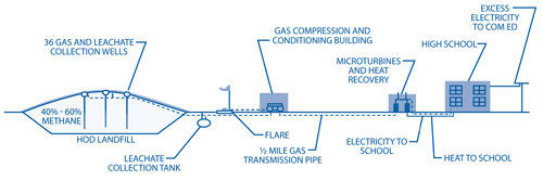
The equipment can generate a total of approximately 360 kW of electric energy and 3.48 million British thermal units (BTUs) of thermal energy to heat and power portions of the 262,000-square-foot school building. The District uses approximately 60% of the power generated during peak hours, and excess electricity produced by the microturbines is transferred to the grid for distribution by Commonwealth Edison (Com Ed).
During installation of the LFG system, improvements were made to the landfill's final cover system. Restoration involved adding a 2-foot layer of compacted clay and a 12-inch layer of non-compacted soil over portions of the site to serve as the upper cover layer. In low-lying areas of the site, the waste was first reconsolidated and then re-covered in a similar manner. Finally, the entire site was regraded to a minimum 2% slope with a maximum 4:1 (horizontal to vertical) ratio on most sides, and vegetation was re-established through seeding and mulching. Approximately two-thirds of the site now hosts many of the school's athletic fields.
Approximately 2,000-3,000 gallons of leachate per day are collected from the dual extraction wells and transported to the publicly owned treatment works for disposal. The current rate of LFG throughput is approximately 150 scfm, with about 48% methane. Turbine efficiency is greatest in colder months. In warmer months, extremely high temperatures within the turbines' metal housings can cause turbine overheating and temporary shutdown; after the temperatures subside, the turbines can be restarted. Although microturbines typically perform best when operating in areas with open air passage, the housings were added as a noise and visual barrier for the campus.
Installed equipment costs for the LFG system totaled approximately $1.9 million, including the $200,000 compression and treatment system, $450,000 pipeline, $1.2 million CHP system, and two new buildings. The cost was offset by a $500,000 grant from the Illinois Department of Commerce and Community Affairs' Renewable Energy Resource Program and secured through revenue bonds. As gas generation declines, individual turbines will be taken offline and sold or re-purposed, and low-cost methods for purchasing second-generation turbines will be explored.
Operational savings due to the first-generation CHP system have been lower than anticipated by the District, with an overall loss to date; however, less electricity and natural gas are purchased than if the system were not in place. To increase overall savings, the District is investigating modifications that could enable certain equipment to operate during off-peak rather than peak electricity hours. Negotiations for net metering of the excess CHP-generated electricity, which would allow potential credit by (or sale to) Com Ed, also are underway.
Contributed by Karen Mason-Smith, EPA Region 5 (mason-smith.karen@epa.gov or 312-886-6150) and Jennifer Nolde, Community High School District #117 (jnolde@d117.org or 847-838-7180)
Coke Production Waste Converted to Synthetic Fuel at West Virginia Superfund Site
EPA Region 3, the West Virginia Department of Environmental Protection (WV DEP), ExxonMobil Corporation, and the Fairmont Community Liaison Panel partnered to incorporate energy production into the environmental restoration of two areas containing byproduct waste from former operations at the Sharon Steel Corporation-Fairmont Coke Works Superfund site in Fairmont, WV. Between 2003 and 2010, coal tar-derived waste materials with high BTU value at the site's former waste management and processing areas were excavated and blended with coal and other materials to form synthetic fuel, or synfuel, for offsite energy recovery. The work was completed as part of Project XL, a program created by EPA in 1995 to test innovative environmental management strategies for achieving a faster, more thorough cleanup.
Coke production, coke waste disposal, and waste treatment operations occurred from 1918 to 1979 on 55 acres of the site. The site's remaining 42 acres comprise a wooded hillside that descends to the Monongahela River. Waste generated during production was disposed of at various onsite locations. Initial emergency response actions were completed in the 1990s, when 1,100 tons of waste tar, over 55,000 tons of waste sludge and debris and more than 330,000 gallons of wastewater were removed from the site. Through Project XL, the majority of the waste materials located in the remaining two areas — the former waste management and former process areas — were integrated into energy production.
The former waste management area encompassed 29 acres in the western portion of the site and comprised two former landfills, oxidation impoundments, a breeze washout area, a waste sludge and breeze storage area, and a sludge storage area. The 10-acre former process area included a breeze pile, a waste tar pit, a benzol scrubber area, gas holders, gas purifier tanks, a phenol recovery building, and a Pyridine sump.
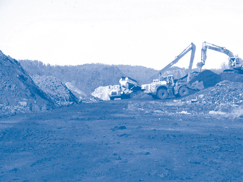
Soil impacted with coal tar-derived constituents and coke breeze was excavated to depths of 18 feet bgs. Excavated materials were placed in temporary staging piles used to sort waste streams (Figure 3). Impacted materials that were deemed unsuitable for synfuel production, such as low-BTU clays and high-sulfur Prussian blue materials, were shipped to permitted offsite treatment, storage, and disposal facilities. Materials with tar-like composition and high BTU value were transported to a processing area where they were screened to remove wood, large rocks, and other debris from the fuel and crushed to achieve a maximum particle size of 3/8-inch diameter for the feedstock. Piles of feedstock were isolated and sampled for parameters of interest. The feedstock was then custom blended with various amendments including coal, coal silts, sawdust, and carbon black to meet fuel feedstock specifications of greater than 7,500 BTU per pound of material with less than 10% moisture, less than 38% ash, and less than 2% sulfur. The feedstock also passed Toxicity Characteristic Leaching Procedure tests. Feedstock specifications were established following a pilot-scale, proof-of-performance, test burn conducted in February 2003 at the Grant Town Power Plant, to confirm that the synfuel product could be processed within existing emission standards.
Onsite processing of excavated materials for synfuel production continued until July 2009, when the larger deposits of potentially recyclable materials at the site had been nearly exhausted. At that point, high BTU-wastes had been processed onsite to generate 486,111 tons of synthetic fuel. The fuel produced in the recycling effort was used at the Grant Town Power Plant to generate over 520,000 megawatts of electricity. When the throughput diminished, the final 6,993 tons of material with greater than 3,500 BTU per pound were transported to the Piney Creek Power Plant in Clarion, PA, where it was blended onsite prior to usage as a power source. In addition, 238,342 tons of contaminated soil and waste with a low BTU value or properties otherwise unsuitable for recycling were transported to permitted offsite facilities for treatment or disposal.
Prior to excavation of materials for synfuel blending, a 50- by 50-foot grid was laid over the entire site. Upon removal of impacted materials, each cell was sampled to verify that chemical-specific performance standards were met within each area to a 95% upper confidence limit. The critical constituents driving the confirmation sampling program were benzene, naphthalene and carcinogenic PAHs measured as benzo(a)pyrene toxicity equivalents [B(a)P TEQ]. Specific performance standards varied slightly between each area but were nominally less than 1.0 mg/kg benzene, less than 0.7 mg/kg naphthalene, and less than 4.6 mg/kg B(a)P TEQ. The cleanup criteria were selected to be protective of underlying groundwater and direct contact with remaining onsite soil. Soil samples collected from the two areas in 2010 confirmed that performance standards had been achieved. The two areas were graded to promote stormwater sheet flow across clean areas, and seeded to control erosion and prevent sedimentation. Deeper excavations were backfilled with clean soil from both onsite and offsite sources.
Recent Reports
EPA's recent report, Superfund Landfill Methane-to-Energy Pilot Project, evaluates the technical and economic feasibility of recovering methane at landfills on six Superfund sites. The methane could be captured to generate electricity for onsite use or sale to a utility, substitute for natural gas used onsite, or fuel gas-fired technologies used by nearby industry. Access the report (OSWER 9200.081) at: www.clu-in.org/greenremediation/subtab_c3.cfm.
A final remedial investigation focusing on groundwater is now underway, and a record of decision is expected in 2012. Redevelopment plans for the site include commercial and recreational use options.
Contributed by Eric Newman, EPA Region 3 (newman.eric@epa.gov or 215-814-3237), Thomas Bass, WV DEP (thomas.l.bass@wv.gov or 304-926-0499 ext.1274), and Michael Lamarre, Exxon Mobil Corporation
