Environmental Geophysics
Well Completion Logging
Logging to determine the construction of a well is useful to plan for cementing operations, installation of casing and screens, hydraulic testing, and guiding the interpretation of other logs. Most of the logs described in other sections of this manual can provide information on well construction under some conditions. They will be listed briefly here so the reader can refer to the detailed descriptions of these logs in the appropriate sections of this manual.
A number of different types of logs can be used to locate cased intervals in wells. Most electric logs will show a sharp deflection at the bottom of a string of steel casing. Resistivity-logging systems that are operating properly will record zero resistivity when all the electrodes are in the casing. Gamma-gamma logs commonly demonstrate a sharp deflection at the bottom of the casing and may shift at depths where a second string of casing is located outside the first; however, such shifts may be difficult to distinguish from changes in hole diameter. High-resolution caliper logs are excellent for locating the bottom of the inside string of casing and threaded couplings. If small arms are used, they also may provide data on casing corrosion and the location of screens and perforations. Care must be taken to assure that the arms do not get caught in screens or perforations.
The acoustic-televiewer is one of the highest resolution devices for obtaining information on casing and screens, but it may be too expensive for some operations. The televiewer must be operated on the mark switch in steel casing, rather than magnetometer, to avoid distortion of the log caused by random triggering. Televiewer logs can provide clear images and accurate locations of screens, perforations, couplings, and damaged casing. Features as small as 1 mm can be resolved under the right conditions. Borehole television can provide some of the same data, but a hard copy of the log is not available for examination at any time. The water in the well also must be clear to allow light transmission.
The casing-collar locator (CCL) is a useful and relatively inexpensive device that can be operated on any logging equipment. The simplest CCL probe contains a permanent magnet wrapped with a coil of wire. Changes in the magnetic properties of material cutting the magnetic lines of flux cause a small DC current to flow, which can be used to drive a recorder channel. The standard mode of operation is to record event marks along the margin of other logs to represent the location of collars in the casing. The event marker is adjusted so that it is triggered when the DC voltage exceeds a certain level. A continuous-collar log can be interpreted in terms of the location of perforations and screens. Corroded casing sometimes can be located by a high-resolution caliper log; spontaneous-potential logs have been used to locate depth intervals where active corrosion is taking place (Kendall, 1965). Commercial logging services are available for detecting corroded casing. An electromagnetic casing inspection log measures changes in the mass of metal between two coils; loss of mass may be due to corrosion (Edwards and Stroud, 1964). A pipe-analysis survey is run with a centralized probe that employs several coils (Bradshaw, 1976). This survey is reported to provide information on the thickness of casing penetrated by corrosion, whether the damage is internal or external, and isolated or circumferential. The electromagnetic-thickness survey measures the average casing thickness over an interval of about 0.6 m and can be used to monitor changes in thickness with time. Casing-inspection logging methods are summarized by Nielsen and Aller (1984).
The location of cement, bentonite, and gravel pack in the annular space outside of casing can be accomplished with several logs, but the interpretation may be ambiguous. A caliper log made before the casing is installed is important to planning cementing or installation of gravel pack. Caliper logs also are useful in interpreting logs run for the purpose of locating annular material, because they indicate the thickness that would be present.
Temperature logs can be used to locate cement grout while it is still warm from setup reactions. Cement-bond logs can be used to locate cement after it has cured, and they may provide information on the quality of the bond between casing and cement and between cement and rock. Uncompensated, short-spaced gamma-gamma logs can indicate the location of cured cement or gravel pack, if a gamma-gamma log was run after installing the casing and prior to filling the annular space; the difference between the two logs may show the filled interval clearly. The pre-cementing gamma-gamma log may resemble the reversed caliper log made prior to installation of the casing. The location of bentonite often is indicated by an increase in radioactivity on gamma logs; however, all bentonite is not more radioactive than the various background materials that might be present.
Acoustic cement bond logging was developed for annular cement evaluation in oil and gas production wells (Bateman, 1985). The interpretation of cement bond logs involves the analysis of the amplitude of the compression wave arrival, and the full waveform display. Where pipe, cement, and formation are well bonded, the full waveform display indicates that the acoustic energy from the logging probe is being transmitted to the formation (a formation response is evident). Furthermore, for the case of continuous cement in the annular space with no voids or channels, the compression wave amplitude is a minimum, increasing where the cement is discontinuous.
A quantitative method employing gamma-gamma density logs calibrated for backfill materials is shown in figure 1 (Yearsley, Crowder, and Irons, 1991). Below the water surface, the saturated sand pack is indicated by a far detector measurement of 1.9 g/cc, and a near detector measurement of 1.7 g/cc, values that were confirmed by physical modeling. The difference in densities between the near and far detectors is due to the greater effect of the low-density PVC on the near detector. The bentonite slurry seal is less dense than the sand pack, and is readily recognized on the geophysical log, but appears to be 3-2/3 m thick rather than the 1-1/2 m specified on the completion schedule. The water surface is identified by an increase in the 4p count rate above a depth of 40 m. Also, note at the water surface, the low densities registered by the near and far detectors and high count rate anomaly on the 4p log, which indicate a washout at that depth. The cement/bentonite grout below the water surface may be indicated by far detector densities greater than 2.0 g/cc, and near detector densities of approximately 1.8 g/cc. The distinct density contrasts above the water surface in figure 395 result from the density differences among grout, unsaturated alluvium, and air voids. Air voids behind the pipe on this log are identified by densities of approximately 1.0 g/cc for both the near and far detectors. Grout above the groundwater surface is interpreted for far detector densities ranging between 1.6 and 2.0 g/cc. The range in density is due primarily to variations in grout thickness. Unsaturated alluvium is indicated by far detector densities between 1.4 and 1.6 g/cc. On the left of figure 1 is a "4p grout line," which indicates the expected 4p count rate in a 10 cm (4-in) PVC air-filled pipe with 6:2 cement:bentonite grout behind the pipe.
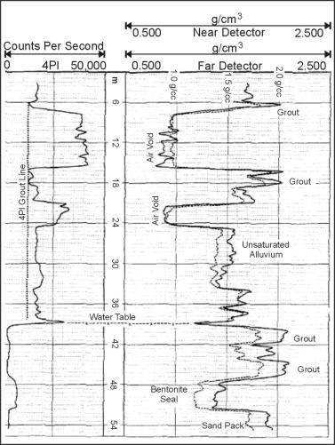
Figure 1. Dual spaced and 4p density logs in a cased monitoring well showing completion as interpreted from the logs. (Yearsley, Crowder, and Irons, 1991; copyright permission granted by Colog, Inc.)
Deviation of drill holes and wells from the vertical is common; it affects proper completion of the well for its intended use, and it may prevent testing and logging. Casing and pumps may be impossible to install in a well that is highly deviated, and centralized logging probes may not function properly in such a well. The deviation seldom is consistent, so that both the angle from the vertical and direction may change rapidly along the borehole. Even auger holes less than 30 m deep have deviated enough that transmittance logs between the holes are adversely affected. Information on borehole deviation is needed to calculate the true vertical depth to features of interest and to correct the strike and dip of fractures or bedding obtained from such logs as the acoustic televiewer.
Continuous logs of hole deviation usually are run by companies that specialize in this technique. Hole-deviation data usually are not recorded by standard logging equipment, except modern dipmeters, which rarely are included on small loggers. A dipmeter log usually includes a continuous record in the left track of the azimuth (magnetic north) and the amount of deviation. Some hole-deviation services provide a printout of azimuth and deviation at predetermined depth intervals, and there are several methods to mathematically describe the path of the deviated hole from these measurements (Craig and Randall, 1976).
The pages found under Surface Methods and Borehole Methods are substantially based on a report produced by the United States Department of Transportation:
Wightman, W. E., Jalinoos, F., Sirles, P., and Hanna, K. (2003). "Application of Geophysical Methods to Highway Related Problems." Federal Highway Administration, Central Federal Lands Highway Division, Lakewood, CO, Publication No. FHWA-IF-04-021, September 2003. http://www.cflhd.gov/resources/agm/
