Environmental Geophysics
Ground-Penetrating Radar
Basic Concept
Ground-penetrating radar (GPR) uses a high-frequency (e.g. 40 to 1,500 MHz) EM pulse transmitted from a radar antenna to probe the earth. The transmitted radar pulses are reflected from various interfaces within the ground, and this return is detected by the radar receiver. Reflecting interfaces may be soil horizons, the groundwater surface, soil/rock interfaces, man-made objects, or any other interface possessing a contrast in dielectric properties. The dielectric properties of materials correlate with many of the mechanical and geologic parameters of materials.
The radar signal is imparted to the ground by an antenna that is in close proximity to the ground. The reflected signals can be detected by the transmitting antenna or by a second, separate receiving antenna. The received signals are processed and displayed on a graphic recorder. As the antenna (or antenna pair) is moved along the surface, the graphic recorder displays results in a cross-section record or radar image of the earth. As GPR has short wavelengths in most earth materials, resolution of interfaces and discrete objects is very good. However, the attenuation of the signals in earth materials is high, and depths of penetration seldom exceed 10 m. Clay materials with a high cation exchange capacity increase the attenuation and decreasing penetration. Additonally, the presence of solutes or other substances which increase the electrical conductance of groundwater and have the same attenuation and penetration results.
The objective of GPR surveys is to map near-surface interfaces. For many surveys, the location of objects such as tanks or pipes in the subsurface is the objective. Dielectric properties of materials are not measured directly. The method is most useful for detecting changes in the geometry of subsurface interfaces.
Geologic problems conducive to solution by GPR methods are numerous and include the following: bedrock configuration, location of pipes and tanks, location of the groundwater surface, borrow investigations, and others. Geologic and geophysical objectives determine the specific field parameters and techniques. Delineation of the objectives and the envelope of acceptable parameters are specified in advance. However, as the results cannot be foreseen from the office, considerable latitude is given to the field geophysicist to incorporate changes in methods and techniques.
The following questions are important considerations in advance of a GPR survey.
What is the target depth? Though target detection has been reported under unusually favorable circumstances at depths of 100 m or more, a careful feasibility evaluation is necessary if the investigation depths need to exceed 10 m.
What is the target geometry? Size, orientation, and composition are important.
a) What are the electrical properties of the target? As with all geophysical methods, a contrast in physical properties must be present. Dielectric constant and electrical conductivity are the important parameters. Conductivity is most likely to be known or easily estimated.
b) What are the electrical properties of the host material? Both the electrical properties and homogeneity of the host must be evaluated. Attenuation of the signal is dependent on the electrical properties and on the number of minor interfaces that will scatter the signal.
c) Are there any possible interfering effects? Radio frequency transmitters, extensive metal structures (including cars) and power poles are probable interfering effects for GPR.
The physics of electromagnetic wave propagation are beyond the scope of this manual. However, there are two physical parameters of materials that are important in wave propagation at GPR frequencies. One property is conductivity (σ), the inverse of electrical resistivity (ρ). The relationships of earth material properties to conductivity, measured in mS/m (1/1,000 Ωm), are given in the section on electrical methods.
The other physical property of importance at GPR frequencies is the dielectric constant (ε), which is dimensionless. This property is related to how a material reacts to a steady-state electric field; that is, conditions where a potential difference exists but no charge is flowing. Such a condition exists between the plates of a charged capacitor. A vacuum has the lowest ε, and the performance of other materials is related to that of a vacuum. Materials made up of polar molecules, such as water, have a high ε. Physically, a great deal of the energy in an EM field is consumed in interaction with the molecules of water or other polarizable materials. Thus, waves propagating through such a material both go slower and are subject to more attenuation.
Earth Material Properties
The roles of two earth materials that cause important variations in the EM response in a GPR survey need to be appreciated. The ubiquitous component of earth materials is water; the other material is clay. At GPR frequencies, the polar nature of the water molecule causes it to contribute disproportionately to the displacement currents that dominate the current flow at GPR frequencies. Thus, if significant amounts of water are present, the ε will be high, and the velocity of propagation of the electromagnetic wave will be lowered. Clay materials with their trapped ions behave similarly. Additionally, many clay minerals also retain water.
The physical parameters in table 18 are typical for the Characterization of earth materials. The range for each parameter is large; thus, the application of these parameters for field use is not elementary.
Simplified equations for attenuation and velocity (at low loss) are:
![]() (1)
(1)
![]() (2)
(2)
where
V = velocity in m/s,
ε = dielectric constant (dimensionless),
a = attenuation in decibels/m (db/m),
σ = electrical conductivity in mS/m.
A common evaluation parameter is dynamic range or performance figure for the specific GPR system. The performance figure represents the total attenuation loss during the two-way transit of the EM wave that allows reception; greater losses will not be recorded. As sample calculations, consider a conductive material (σ = 100 mS/m) with some water content (ε=20). The above equations indicate a velocity of 0.07 m per nanosecond (m/ns) and an attenuation of 38 dB/m. A GPR system with 100 dB of dynamic range used for this material will cause the signal to become undetectable in 2.6 m of travel.
The transit time for 2.6 m of travel would be 37 to 38 ns. This case might correspond geologically to a clay material with some water saturation. Alternatively, consider a dry material (ε=5) with low conductivity (σ = 5 mS/m). The calculated velocity is 0.13 m/ns and the attenuation is 3.8 dB/m, corresponding to a distance of 26‑27 m for 100 dB of attenuation and a travel time of 200 ns or more. This example might correspond to dry sedimentary rocks.These large variations in velocity and especially attenuation are the cause of success (target detection) and failure (insufficient penetration) for surveys in apparently similar geologic settings. As exhaustive catalogs of the properties of specific earth materials are not readily available, most GPR work is based on trial and error and empirical findings.
Table 1. Electromagnetic properties of earth materials.
| Material | E | Condutivity |
Velocity, (m/ns) |
Attenuation, (dB/m) |
| Air | 1 | 0 |
0.3 |
0 |
| Distilled Water | 80 | 0.001 |
0.033 |
0.002 |
| Frest Water | 80 | 0.5 |
0.033 |
0.1 |
| Sea Water | 80 | 3,000 |
0.01 |
1,000 |
| Dry Sand | 3-5 | 0.01 |
0.15 |
0.01 |
| Wet Sand | 20-30 | 0.1-1 |
0.06 |
0.03-0.3 |
| Limestone | 4-8 | 0.5-2 |
0.12 |
0.4-1 |
| Shales | 5-15 | 1-100 |
0.09 |
1-100 |
| Silts | 5-30 | 1-100 |
0.07 |
1-100 |
| Clays | 5-40 | 2-1,000 |
0.06 |
1-300 |
| Granite | 4-6 | 0.01-1 |
0.13 |
0.01-1 |
| Dry Salt | 5-6 | 0.01-1 |
0.13 |
0.01-1 |
| Ice | 3-4 | 0.01 |
0.16 |
0.01 |
| Metal |
Modes of Operation
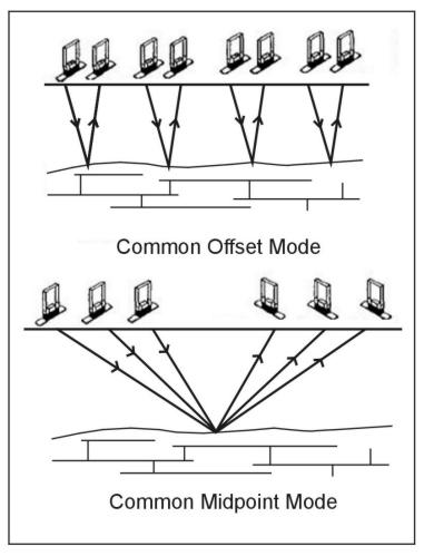
The useful item of interest recorded by the GPR receiver is the train of reflected pulses. The seismic reflection analogy is appropriate. The two reflection methods used in seismic reflection (common offset and common midpoint) are also used in GPR. Figure 1 illustrates these two modes. A transillumination mode is also illustrated in the figure, which is useful in certain types of nondestructive testing. The typical mode of operation is the common-offset mode where the receiver and transmitter are maintained at a fixed distance and moved along a line to produce a profile (figure 2). Note that as in seismic reflection, the energy does not necessarily propagate only downwards, and a reflection will be received from objects off to the side. An added complication with GPR is the fact that some of the energy is radiated into the air and, if reflected off nearby objects like buildings or support vehicles, will appear on the record as arrivals.
Data Acquisition
Historically, a GPR crew consists nominally of two persons. One crew person moves the antenna or antenna pair along the profiles, and the other operates the recorder and annotates the record so that the antenna position or midpoint can be recovered. Recent innovations have made the application of GPR to may scenarios a one person job, by allowing for cart based applications.
The site-to-site variation in velocity, attenuation, and surface conditions is so large that seldom can the results be predicted before fieldwork begins. Additionally, the instrument operation is a matter of empirical trial and error in manipulating the appearance of the record. Thus, the following steps are recommended for most fieldwork:
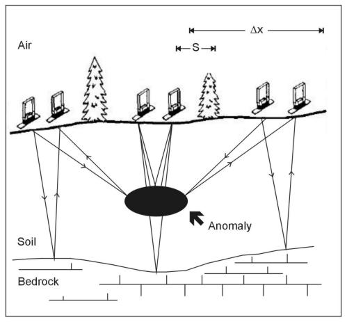
Figure 2. Schematic illustration of common offset single-fold profiling.

Figure 3. GPR received signal and graphic profile display. (Benson, Glaccum, and Noel, 1983)
1. Unpack and set up the instrument and verify internal operation.
2. Verify external operation (one method is to point the antenna at a car or wall and slowly walk toward it. The reflection pattern should be evident on the record).
3. Calibrate the internal timing by use of a calibrator.
4. Calibrate the performance by surveying over a known target at a depth and configuration similar to the objective of the survey (considerable adjustment of the parameters may be necessary to enhance the appearance of the known target on the record).
5. Begin surveying the area of unknown targets with careful attention to surface conditions, position recovery, and changes in record acter.
Often a line will be done twice to be sure that all the features on the record are caused by the subsurface.
Data Interpretation
Because of the strong analogy between seismic reflection and GPR, the application of seismic processing methods to GPR data is a fertile field of current research. Such investigations are beyond the scope of this manual. The focus herein is on the most frequent type of GPR survey, i.e., location of specific targets.
GPR surveys will not achieve the desired results without careful evaluation of site conditions for both geologic or stratigraphic tasks and target-specific interests. If the objectives of a survey are poorly drawn, often the results of the GPR survey will be excellent records that do not have any straightforward interpretation. It is possible to tune a GPR system such that exceptional subsurface detail is visible on the record. The geologic evaluation problem is that, except in special circumstances (like the foreset beds inside of sand dunes), there is no ready interpretation. The record reveals very detailed stratigraphy, but there is no way to verify which piece of the record corresponds to which thin interbedding of alluvium or small moisture variation. GPR surveys are much more successful when a calibration target is available. GPR can be useful in stratigraphic studies; however, a calibrated response (determined perhaps from backhoe trenching) is required for geologic work.
Figure 4 indicates that localized objects will produce a hyperbola on the record. The hyperbolic shape is due to reflection returns of the EM pulse before and after the antenna system is vertically above the target. The shortest two-way travel distance is when the antenna (or center of the antennae pair) is on the ground surface directly above the object. All other arrivals are at greater distances along a different hypotenuse with each varying horizontal antenna location. This hyperbola is also important for the determination of the radar velocity.
Figure 5 is the schematic of a set of targets surveyed by GPR. The record section of figure 6 indicates the excellent detection of the targets. Figure 7 displays an example of three dimensional GPR data acquisition for concrete inspection.
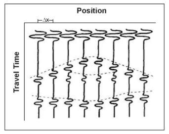
Figure 4. Format of a Ground Penetrating Radar reflection section with radar events shown for features depicted in figure 2.
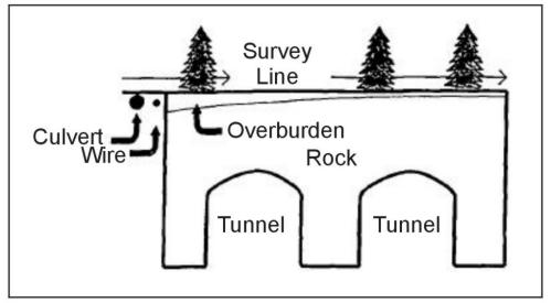
Figure 5. Schematic of a set of targets surveyed by Ground Penetrating Radar.
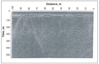
Figure 6. Actual GPR record over a culvert, pipe, and two tunnels showing the hyperbolic shape of the reflected/diffracted energy. (Annan, 1992)
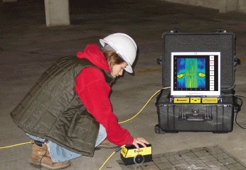
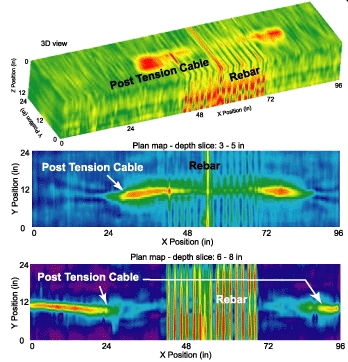
Figure 7. A worker images rebar and post tension cables within concrete using high frequency GPR in a 3D grid. A 3D GPR block of data shows the contrasting response from the rebar and post tension cables. Two depth sllices from the 3D block display plan view location of the rebar and post tension cables. These images are presented for references purposes only, no endorsement of the equipment or software manufacturer is intended (http://www.sensoft.ca/applications/structure/casestudy/cs_tensioncables.html).
GPR Case Histories
GPR has been widely used, and reports on its effectiveness are available both in government and professional web manuals. Some useful references are:
Daniels et al. (1995) used GPR applied to remdiation monitoring.
Huisman et al., (2002) used GPR in an agricultural application.
Butler (1992), which is the proceedings of a GPR workshop and includes a tutorial and a collection of case histories.
Butler, Simms, and Cook (1994), which provides an archaeological site evaluation.
Sharp, Yule, and Butler (1990), which reports the GPR assessment of an HTRW site.
The pages found under Surface Methods and Borehole Methods are substantially based on a report produced by the United States Department of Transportation:
Wightman, W. E., Jalinoos, F., Sirles, P., and Hanna, K. (2003). "Application of Geophysical Methods to Highway Related Problems." Federal Highway Administration, Central Federal Lands Highway Division, Lakewood, CO, Publication No. FHWA-IF-04-021, September 2003. http://www.cflhd.gov/resources/agm/
